ABIT BH7 (845PE): Entry Level 800MHz FSB
by Evan Lieb on April 6, 2003 6:56 PM EST- Posted in
- Motherboards
ABIT BH7: Board Layout
In general we liked the ABIT laid out their new BH7 motherboard, as most of our criteria for a convenient layout were met.
The ATX (20-pin) connector is located right where we usually like it to be, near the top right-hand corner of the PCB. Positioning the ATX (20-pin) connector in this way can prevent a basic PSU (power supply unit) thick ATX wires from obstructing the installation/uninstallation of the CPU HSF, passive North Bridge heatsink or any other components that you may decide to modify or uninstall in that general area. The ATX (20-pin) connector's position is less important if you own a high quality PSU from, for example, Enermax or Antec because these PSU's always have extra-long ATX cables that can be tucked away from obstructing motherboard components.
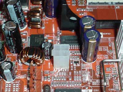
The ATX12V connector is located a bit too closely to the lower left-hand portion of the CPU clamps and therefore will cause a bit of an annoyance if you want to install/uninstall a CPU heatsink. What makes this an annoyance isn't just the ATX12V connector's position but the fact that a tiny capacitor sits right next to the ATX12V's clamp, requiring either a tool or tiny fingers to unhinge the ATX12V line.
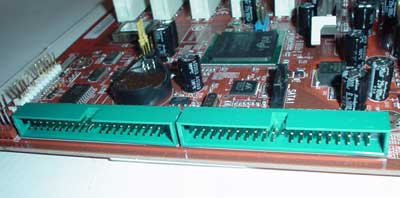
The Primary and Secondary IDE connectors are placed very awkwardly on the BH7. For some reason they're both placed horizontally and at the edge of the PCB. This is awkward because you have to twist your IDE cables while colluding with a long video card to get them to the upper bays of an ATX case for connection to an optical drive. If ABIT had included rounded IDE cables this might not be an issue, but since they didn't it is something worth noting. We usually like to see the Primary and Secondary IDE connectors higher up on the right-hand portion of the PCB so that IDE cable length and clutter doesn't become an issue. On the whole however, it's certainly not the worst Primary/Secondary IDE connector location we've seen.
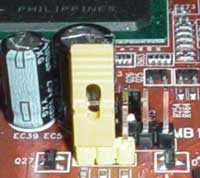
It's well known that most ABIT motherboards cater to enthusiasts/experts of the hardware world. This is illustrated in a tiny way with their CMOS jumper, which has been elongated more than normal. This is helpful in that people of any size fingers can reset the CMOS jumper without issue, as isn't always the case with CMOS jumper sizes. For overclockers this is especially useful, as clearing the CMOS can become a common activity for them.
Thankfully the DIMM connectors aren't located too close to the ASUS GeForce4 Ti4600 video card we installed. The DIMM connectors are far enough away from the AGP slot so that you can stick your finger in between them; this allows the user enough room to install/uninstall memory without being forced to uninstall the video card, VGA screw, and VGA adapter.


0 Comments
View All Comments