Gigabyte 7VAXP-A Ultra: The KT400A in Retail Action
by Evan Lieb on March 31, 2003 3:19 AM EST- Posted in
- Motherboards
Gigabyte 7VAXP-A Ultra: Board Layout
The 7VAXP-A Ultra has a somewhat unique layout compared to the latest high-end motherboards on the market. Let's get started….
First off, the ATX (20-pin) connector is right where we like it, on the right-hand side of the motherboard above the Primary and Secondary IDE connectors. We continue to praise this type of positioning because thick ATX wires can obstruct the installation/uninstallation of the CPU HSF in addition to any other components that might be modified around that area. One of those areas are where the mounting holes should have been, but that Gigabyte decided to opt against. Users looking to install higher quality MCX and PAL heatsinks will be disappointed with the 7VAXP-A Ultra, but there's always other screwless options like the Volcano 7+ series of heatsinks with fan-control and copper construction that attaches directly to the CPU socket.
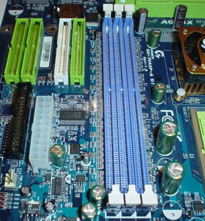
The Primary and Secondary IDE connectors are positioned exactly where we like them; above the AGP slot and to the right. This time though Gigabyte pushes the Primary and Secondary IDE connectors a bit further towards the middle of the PCB, and this is where it gets a bit messy. If you use both or one of the Primary/Secondary connectors, your IDE cables will be colliding with the main ATX (20-pin) cable's wires, since Gigabyte pushes the Primary/Secondary connectors closer to the middle of the PCB. This can be quite a nuisance for the neat freaks out there.
The reason the Primary and Secondary IDE connectors were placed closer to the middle of the PCB was due to both IDE RAID connectors, placed about half an inch to the right of the Primary and Secondary IDE connectors. While this isn't bad in of itself, the Floppy connector complicates things quite a bit. The Floppy connector is located above the IDE RAID connectors, a couple centimeters to the right of the ATX connector. This isn't a totally ideal location if you plan on having a Floppy drive as well as a neat case; the Floppy cable will have to travel through the Primary/Secondary IDE cables and IDE RAID cables (if you've setup a RAID array of course) and then under them a bit to reach the Floppy drive bay. So while we don't like the Floppy connector location, the Primary/Secondary and RAID connectors are placed well enough so that cable length will be of no concern.
The DIMM connectors are also placed excellently. The DIMM connectors did not interfere with the long GeForce4 Ti4600 video card installed in the 7VAXP-A Ultra's AGP slot. This is nice to see as you aren't forced to uninstall your video card if you need to add memory to your system. An example of a common scenario where you might need to add memory to your system while your video card is installed is when you're upgrading your system for the first time in quite a while, and you decide to add a large stick of high-speed memory to boost application performance.
There are two USB 2.0 headers and three FireWire headers located at the bottom of the 7VAXP-A Ultra, colored in yellow and grey. This is a good place to position the USB 2.0 and FireWire headers, as the wires from a USB 2.0/FireWire bracket won't collide with any other PCI cards you may or may not decide to install in your motherboard, in addition to any other components that may stick out. So in general, these locations will help to reduce clutter, which is nice.


0 Comments
View All Comments