MSI 655 Max: Board Layout
The MSI 655 Max has a very unique layout, though that doesn't mean we didn't have any complaints.
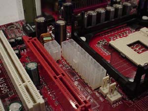
The main ATX (20-pin) connector is located in a very unique position. Instead of being on the left or right-hand side of the motherboard, it's placed smack in the middle of the motherboard, just below the CPU clamps. This positioning is pretty inconvenient for users looking to install/uninstall their HSF or any other components in that area, as the ATX wires may obstruct their path. In addition, it's very difficult to unhook the ATX connector with the HSF installed because the ATX connector is placed so close to the CPU clamps.
The ATX12V connector runs into the same issue as the ATX connector does. It's simply placed much too closely to the CPU clamps. Though it's not so close that it's difficult to unhook, it's positioned poorly enough that it runs over the HSF among other components.
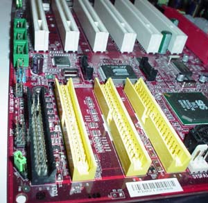
The Primary and Secondary IDE connectors aren't placed too well either. In fact, the Primary and Secondary IDE connectors are placed almost at the bottom of the motherboard near the USB and FireWire headers. With this location it becomes nearly impossible to install an optical drive in the uppermost bays of a full ATX case. However, we were happy to see the Floppy connector in the correct location (below the IDE connectors), as this is the most clutter-free route you can take.
Normally, poor DIMM connector positioning is an annoying fact of life with most motherboards. However, the MSI 655 Max is an exception. Instead of the DIMM slots being positioned parallel to each other like 99% of the motherboards out there, they are positioned perpendicular to each other. MSI did this simply because SiS' reference design for the 655 was exactly that. MSI tells us that the only reason the DIMM slots are positioned this way is because SiS wanted to keep the trance length the same between the DIMM slots and the North Bridge. Without equal trace length you can yield timing problems, and this is especially true of dual channel DDR timing.
Still, two of the four DIMM connectors are too close to the video card assuming you're using a GeForce4 Ti4600 length card. If not, then the DIMM connector location shouldn't be an issue whatsoever.
The USB and FireWire headers are one of the few features located fairly well. Since these headers are located at the very bottom of the board, their bracket wires won't clutter up other PCI cards or components in that area. This is a nice thing to have, as case clutter can be quite annoying if you frequently update and/or mod your system.


1 Comments
View All Comments
gustavlasko - Friday, April 16, 2004 - link
Things must have changed since this article is written and now. I myself had to RMA a board that I bought off ebay with MSI. It was a painless process, altough it did take about a month altogether until the board was back, but I had no problems whatsoever with their customer support.