Gigabyte Z77X-UP4 TH Review: Thunderbolt Times Two
by Ian Cutress on September 17, 2012 11:00 AM EST- Posted in
- Motherboards
- Gigabyte
- Z77
- thunder
Gigabyte Z77X-UP4 TH Overclocking
Note: Ivy Bridge does not overclock like Sandy Bridge. For a detailed report on the effect of voltage on Ivy Bridge (and thus temperatures and power draw), please read Undervolting and Overclocking on Ivy Bridge.
Experience with Gigabyte Z77X-UP4 TH
Our last overclocking experience on a Gigabyte board with Ultra Durable 5 was not a true indication of whether this enhanced power delivery affects overclocking – we were artificially limited by the weak BIOS for that review. Results for the Z77X-UP4 TH though were able to stretch our Ivy Bridge CPU more to the limit. In our manual overclocking, we even hit a magical 4.8 GHz stable, albeit nudging 100°C on our Intel AIO cooler.
The automatic overclocking using EasyTune6 was simple to handle – each overclocking ‘level’ of presets worked by default. Auto Tuning was a different matter with the system happily trying to ramp up to nearly 5 GHz before crashing spectacularly and not retaining any settings.
Overall the Ultra Durable 5 element of this board did give a sense of stability, though the lack of actual voltage reporting did not allow us to probe if Load Line Calibration was being strong and true or pushing the voltage over our settings (like on the EVGA Z77 FTW).
Methodology:
Our standard overclocking methodology is as follows. We select the automatic overclock options and test for stability with PovRay and OCCT to simulate high-end workloads. These stability tests aim to catch any immediate causes for memory or CPU errors.
For manual overclocks, based on the information gathered from previous testing, starts off at a nominal voltage and CPU multiplier, and the multiplier is increased until the stability tests are failed. The CPU voltage is increased gradually until the stability tests are passed, and the process repeated until the motherboard reduces the multiplier automatically (due to safety protocol) or the CPU temperature reaches a stupidly high level (100ºC+).
Our test bed is not in a case, which should push overclocks higher with fresher (cooler) air. We also are using Intel's All-in-one Liquid Cooler with its stock fan. This is a 120mm radiator liquid cooler, designed to mimic a medium-to-high end air cooler.
Automatic Overclock:
For our automatic overclocking, options are available through the EasyTune6 software. The initial screen presented in ET6 gives three overclock levels to choose from, or a big red ‘Auto Tuning’ button:
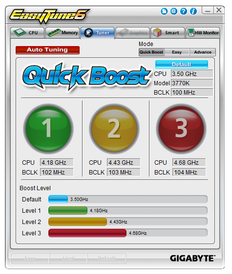
Here are our results:
At ET Level 1, the system applied a 41x multiplier and a 102 MHz BCLK for a total of 4.18 GHz. This was paired with a CPU voltage offset of +0.150 volts and left LLC on automatic. In this scenario, the system showed a load voltage in the OS of 1.062 volts, and peak temperatures of 81ºC during PovRay and 82ºC during OCCT.
At ET Level 2, the system applied a 43x multiplier and a 103 MHz BCLK for a total of 4.43 GHz. This was pared with a CPU voltage offset of +0.150 volts and left LLC on automatic. In this scenario, the system showed a load voltage in the OS of 1.068 volts, and peak temperatures of 82ºC during PovRay and 85ºC during OCCT.
At ET Level 3, the system applied a 45x multiplier and a 104 MHz BCLK for a total of 4.68 GHz. This was pared with a CPU voltage offset of +0.150 volts and left LLC on automatic. In this scenario, the system showed a load voltage in the OS of 1.068 volts, and peak temperatures of 93ºC during PovRay and 95ºC during OCCT.
When Auto Tuning was selected, the system rebooted under XMP settings, then performed stress tests increasing both the multiplier and the BCLK. At 48x and 103.3 MHz, the system rebooted to ET Level 2 and accepted that overclock. Sometimes Auto Tuning would fail completely, or cause the BIOS to bring up the failed boot screen.
Manual Overclock:
For a manual overclock, the user can either adjust settings in EasyTune6 or adjust the BIOS settings. The BIOS settings are a little strewn about the place, with the CPU frequencies and voltages being in separate menus, as well as LLC settings. For finer tuning of the memory, the user has to navigate back out of the CPU or voltage menus then into the memory menu.
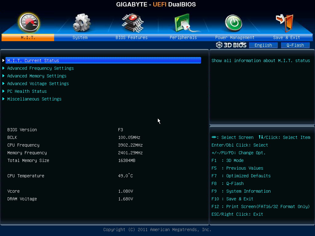
As with our standard testing procedure, we start with 1.100 volts set in the BIOS under the top level of LLC (Extreme), and from the 44x multiplier stress test each multiplier until unstable, then up the voltage to achieve stability. Due to the BIOS voltage reporting issues mentioned previously, the load voltage reported in the BIOS at each stage was 1.068 volts, suggesting that somewhere along the line the voltage readout is being manipulated or not passed to the OS properly. Here are our results.
At the 44x multiplier with a BIOS setting of 1.100 volts, the system was stable with peak temperatures of 71ºC during PovRay and 72ºC during OCCT.
At the 45x multiplier, the system was stable at a BIOS setting of 1.100 volts. Peak temperatures reported were 70ºC for PovRay and 73ºC for OCCT.
At the 46x multiplier, the system was stable with a minimum BIOS setting of 1.150 volts. Peak temperatures reported were 77ºC for PovRay and 78ºC for OCCT.
At the 47x multiplier, the system was stable with a minimum BIOS setting of 1.200 volts. Peak temperatures reported were 84ºC for PovRay and 86ºC for OCCT.
At the 48x multiplier, the system was stable with a minimum BIOS setting of 1.300 volts. Peak temperatures reported were 100ºC for PovRay and 101ºC for OCCT.
Other multipliers were not tested due to the temperatures being reached.


15 Comments
View All Comments
IanCutress - Monday, September 17, 2012 - link
I have access to a TB device, but it is only the two-bay Little Big disk with a pair of Intel Drives. Can't really stress the TB implementation in terms of peak speeds, and in our copy test it can get anything from 1.1 seconds to 3.3 seconds depending on if the wind is blowing, or the tides are in (very unpredictable).When I can get a 4-bay TB device in, I will fill it with 500MB/s+ SSDs and get down to testing. Unless there is a specific test you would like me to do (4K et al).
Ian
repoman27 - Monday, September 17, 2012 - link
I am very curious about a couple points, however they are not the easiest scenarios to test.Firstly, GIGABYTE depicts the ability to support a total of 12 connected Thunderbolt devices plus 2 displays, or 6 devices AND 1 display per port. [ http://www.gigabyte.com/microsite/306/images/thund... ] This seems to fly in the face of what we have been told by Apple and Intel about supported topologies, i.e. "up to a total of 6 devices, including up to 2 high resolution DisplayPort v1.1a displays". Can a single Cactus Ridge DSL3510L really handle that many devices? Is there some difference in implementation between Windows and Mac OS?
GIGABYTE also claims a full 10 Gbps of PCIe bandwidth from each port. Now I would also doubt that claim, and in the article you indicated this wasn't happening with a single DSL3510L. However, Anand achieved 1380 MB/s by using both Thunderbolt ports during his review of the MBPR, which also uses just one DSL3510L controller. Now ultimately this controller is bound by its PCIe 2.0 x4 back end, which should limit it to around 1600 MB/s of payload throughput, but breaking the 1000 MB/s barrier would seem to imply that there is more than one PCIe to Thunderbolt protocol adapter in these Cactus Ridge chips. This would be significant if true. Any chance you could lean on it hard enough to find out?
goinginstyle - Monday, September 17, 2012 - link
I agree about the need for TB testing as I have had nothing but issues with this board and a Seagate GoFlex attached on one port and a Apple TB 27" monitor on the other port. The monitor will flicker badly at times (does not happen on a competing board and a MacBook Pro) while the Seagate drive will "disappear" and requires a power on/off before being recognized again.thewhat - Tuesday, September 18, 2012 - link
It would be great if you could test with Speedfan whether the fan speed can be controlled independently for every header.NiggaASD - Sunday, December 9, 2012 - link
Ian, I think you are wrong about Gigabyte manipulating CPU voltage readings. The voltage reading 1.068 V is probably not CPU vcore, it could be VTT(VCCIO) voltage. It is known that some GB motherboards have this "feature", that they show VTT voltage in CPU-Z. For example, my GA-P67A-UD3P-B3 board shows 1.092 V in CPU-Z as vcore when I have set VTT to 1.1 V in BIOS.