Budget Micro-ATX P55 Faceoff: Gigabyte GA-P55M-UD2 and ASRock P55M Pro
by Gary Key on October 5, 2009 12:30 PM EST- Posted in
- Motherboards
Overclocking
GIGABYTE advertises the GA-P55M-UD2 as an entry level P55 motherboard and will nudge users towards their enthusiast-oriented UD4P or UD5 series for overclocking duties. We are here to say that on most air-cooling or even water-cooling setups, it makes no difference whether you are using this board or one of the $220+ P55 boards. They all tend to reach the same 210~220 Bclk range with memory hitting 2133 or a little higher. The primary differences between the “entry-level” boards and the more expensive enthusiast level boards will be in memory overclocking, BIOS features, and possibly stability at the higher Bclk rates.
Now, memory overclocking really only matters for setting benchmark records, the additional BIOS features is something most everyone can live without, and stability in reaching a 222MHz Bclk compared to 215MHz Bclk (on air) will only matter to those who like to post CPU-Z screenshots or run SuperPi/3DMarks as their primary applications. For those on advanced cooling, the more expensive boards are designed to handle those requirements, but you are not going to run your system 24/7 with these cooling methods and probably want an i7/X58 platform for that purpose anyway.
So for those of us on a budget but still wanting a very good overclocking experience, the Gigabyte P55M-UD2 will cover just about every need one can ask for in a P55 motherboard. We expected solid overclocking based on the BIOS design and board components, but this board clocked just as well or better than any upper-end P55 boards we have in the labs.
True, there are boards that will hit higher Bclk rates or offer better memory performance, but we are concentrating on practical overclocking capabilities in our tests. We focus on the type of overclocks that support 24/7 operation with reasonable cooling and the ability to run a multitude of programs without a problem. We are not optimizing for SuperPi, 3DMark records, or to get that one extra Bclk for a CPUZ screenshot. We put an emphasis on stability during our testing sessions so we test with real world applications ranging from a variety of games to digital imaging software to various audio/video creation programs, and 3D rendering programs in multitask situations.
We have tested a variety of retail Core i5/750 processors over the past several weeks. Our particular sample (L926B) used in testing will hit 4.1GHz with decent air cooling on 1.375V VCore on average. Some boards require less voltage and some require more, but we consider 1.375V to be the median average. The latest retail processors (L928B) are running at 4.2GHz on the same voltage but we have already completed testing with the earlier stepping. Of course, getting a really good retail CPU is a roll of the dice for the most part.
As much as most motherboard suppliers would like you to believe that the board design and cost is going to have the greatest impact on overclocking, that is really not true with the Lynnfield/P55 platform with air or water cooling. The most significant impact on overclocking this platform will be directly attributable to the quality of the CPU and your cooling choice, provided your motherboard has overclocking options.
We tend to keep to our voltages around 1.375V with the Lynnfield processors and air cooling as heavy load multitask temperatures will reach around 80C with very good air cooling. Typical gaming situations and single task application usage will see temperatures hit the 57C~65C range under full load conditions over a period of an hour or so. We could add more voltage, but with our current 750, it would only get us to 4.2GHz and any performance differences are not noticeable without a benchmark.
Core i5/750 8GB Results
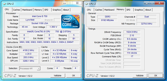
Our maximum stable overclock on air-cooling with the Core i5/750 resulted in a 4.1GHz clock speed at a respectable 205MHz Bclk with a variety of 8GB DDR3-2000+ memory kits from G.Skill , Patriot, OCZ, Kingston, and Corsair. The primary voltages settings were 1.375V VCore, 1.37V VTT, 1.80V PLL, and 1.66V VDimm.
In the end, we settled on 20x205. Our Patriot and Kingston memory kits would run either at 8-9-8-24 2T or 9-9-9-24 1T on 1.66V, increasing voltage did not allow us to run 1T at CAS8 with these lower binned Elpida Hyper kits. However, performance was identical between the two settings. Vdroop was approximately -.005V with Load Line Calibration (LLC) enabled and -.01V with it disabled at idle. Under load Vdroop was -.015V with LLC enabled and -.03V with it disabled.
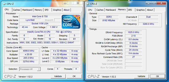
We could increase Bclk to 215 and drop our CPU multiplier to 19, but that required a VTT increase to 1.41V, memory to 1.70V (due to the increased memory speed) , and PLL to 1.86V. Performance was not any different from our 20x205 setting in application testing. In fact, dropping our memory multiplier to 8x for a DDR3-1720 setting resulted in timings at 7-7-7-20 1T at 1.64V and VTT dropping to a decent 1.350V range. Application performance was generally the same between the two memory settings and at times favored the DDR3-1720 C7 setup.
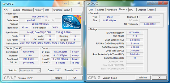
Core i7/860 8GB Results
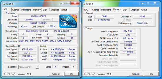
Our i7/860 fared better clocking wise than the i5/750. We ended up at a perfectly stable 21x205 setting resulting in a 4.3GHz clock speed with 8GB at DDR3-2050 at 9-9-9-24 1T timings. However, our voltage settings changed a little with VTT at 1.39V, PLL at 1.86V, VDimm at 1.66V, and VCore at 1.375V. Under load Vdroop was -.015V with LLC enabled and -.03V with it disabled.
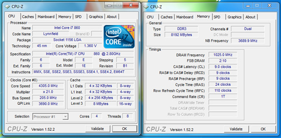
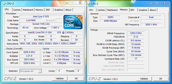
Core i7/870 8GB and 4GB DDR3-2400 Results
We know most people will not purchase the Core i7/870 and if they do, it is probably not going into a $110 motherboard. Our intent in showing this screenshot is that we simply left all of the voltage settings on auto except for VDimm. It took about ten seconds in the BIOS to get this overclock. The board settings were extremely close to our manual settings with the exception being VTT and VDimm.
VTT was set to 1.41V which is acceptable for this overclock level and memory settings, manually this clock speed needed 1.39V VTT. The problem was with VDimm, as soon as the memory clocks exceeded 2000, the board would auto set to 1.80V. That voltage is something our Elpida Hyper IC kits do not like. We ended up changing VDimm to 1.66V.
Gigabyte advertised DDR3-2400 speeds so we decided to verify their claim. Sure enough, the board had no problem running our OCZ DDR3-2400 Blade kit at 2400 with the stock 9-10-9-24 1T settings on 1.66V.


Thoughts
We have absolutely no concerns about recommending this board for 24/7 overclocking use. This board overclocks Core i7 processors just as easily as it does the Core i5 offerings, which is a feat several of the upcoming budget/mid-range P55 boards cannot accomplish. To be honest here, overclocking a Lynnfield processor is extremely easy; really, you only need to worry about VCore, VDimm, VTT, and occasionally PLL settings. If you get a really good CPU, such as our current i7/860 sample, it makes overclocking really easy, even if you just woke up from a coma and your last memory was playing pong at a disco club. What made our overclocking experience enjoyable was the fact that this board is so easy to operate with up to its limits. It simply is a great motherboard to own for quick and stable overclocks.
In regards to voltage regulation, we think the GA-P55M-UD2 has very
good voltage output. We checked all the major voltages with a DMM and found
very little variance between what you select in the BIOS and what the board
actually outputs. The VTT, PLL, DIMM, and other voltages are accurate and
stable across the spectrum until you hit the upper limits of current draw. As a side bonus, S3 resume worked perfectly with Bclks up to 215.
This is not a board to have for extreme clocking as I would not run CPU voltages higher than 1.45V on it without expecting something to fail, rather quickly I might add. It is perfectly suited for air-cooling and typical water cooling setups and one should not expect more. I was initially concerned about the lack of passive MOSFET cooling. With our voltage settings and stated goal of practical overclocking for the majority of users, it is not a problem, even with the Core i7/860 at 4.3GHz under full load. We typically measured MOSFET temps around 61C at 4.3GHz and around 58C at 4.2GHz without any direct airflow over the board. I would still recommend a well ventilated case for these types of overclocks.


55 Comments
View All Comments
goinginstyle - Monday, October 5, 2009 - link
I loved the review also and it showed a lot of work went into testing these boards. I just wonder when TA152H is going to ruin this thread but until then it nice to see constructive posts. I also wish the mobo guys would just drop the floppy and IDE ports when possible. It would free up board real estate and hopefully drop the cost a little more.papapapapapapapababy - Monday, October 5, 2009 - link
not touching any of this at least it has Socket 775 mounting holesusb3 @ pci3 @sata6 and im there.
Docket - Monday, October 5, 2009 - link
It is a shame that there are no Linux versions of the Gigabyte software reviewed here... oh well maybe some day in a distant future.mitt - Monday, October 5, 2009 - link
Hallelujah! DPC latency benchmark in AnandTech reviews!mathew7 - Monday, October 5, 2009 - link
When MB manufacturers are going to let go of PCI?I recently switched to Micro-ATX, and found I have a real problem of choosing a motherboard.
I'm looking at buying a PCIe X-Fi, but would like to use a dual-slotted video card. But I would like to keep my options open for a second card (I'm htinking about physics, not SLI/CF, so dual-slot cooling is not required). While the Gigabyte does not pass my requirements, the Asrock also has a problem: usage of a dual-slot-cooled card inhibits the usage of the PCIex1 slot.
I intend to switch to i5/P55 at the start of next year, so I'm watching closely.
Jaybus - Thursday, October 8, 2009 - link
That will be a slow transition. There are still a lot of PCI adapters being sold out there, especially for some specialty markets like scientific instrumentation that take time to transition to new interfaces due to cost and low volume. Nevertheless, the demise of PCI is starting to happen. For most people it's not a big deal, because they only need 1 or 2 PCIe x16 slots for graphics cards and will never use the rest of the slots anyway.MadMan007 - Monday, October 5, 2009 - link
Kind of funny but Intel is leading the pack in that specific area, their $200 (ugh) 'Extreme' DP55SB mATX P55 mobo has no PCI slots, also no PS/2, IDE or floppy. Maybe it's consistent since they ditched PS/2 and other legacy connectors on some boards a while back. No telling on the overclocking front but it is an 'extreme' board so it may have at elast some overclocking features. It has a couple of neat features actually, Bluetooth and Intel NIC.Jaybus - Thursday, October 8, 2009 - link
And uATX is a good platform to remove PCI from. Why not drop it from uATX? They can always leave it on ATX boards for a while for those who absolutely need PCI slots. I think other manufacturers will follow that path very soon.MadMan007 - Monday, October 5, 2009 - link
*bzzt* The only PCIe 2.0 lanes on a P55 platform are from the CPU. So look carefully at specs and double check with companies when they say their secondary slots, especially ones that aren't even 16x mechanical, are PCIe 2.0. The UD2's 4x electrical slot in particular is clearly not according to Gigabyte, the ASRock claims to be but I'm not sure how if all 16 CPU PCIe 2.0 lanes are used for the graphics slot. If they used a lane splitter to provide PCIe 2.0 lanes to the other slots it kind of defeats the purpose, and if so it would be good to check performance with those slots populated.MadMan007 - Monday, October 5, 2009 - link
To follow up on this, the comment was based on the first few paragraphs. I looked over Intel's manual for their 'extreme' mATX board for my post about it and Intel actually states their mobo has PCIe 2.0 lanes to the additional PCIe slots. Not surprising for the 8x slot I guess but it is for the 1x slots and it seems unlikely Intel would misquote specs.On a related note there is one thing I've not seen yet from any review and that is how PCIe lanes get assigned, mainly to the primary 16x slot, when populating a secondary PCIe slot with a 1x or 4x card. Do the lane splitter chips assign 8x lanes to a secondary slot which has a 1x or 4x card or what? Not a huge deal but it's a little thing that would be nice to know.