EVGA X58 Classified - First Look
by Rajinder Gill on February 27, 2009 5:00 AM EST- Posted in
- Motherboards
More BIOS Stuff
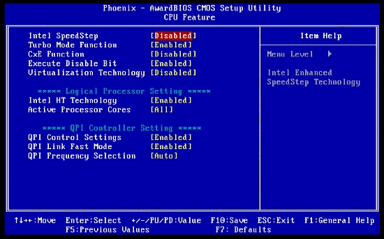
Intel SpeedStep: You can set this to Enabled for 24/7 overclocking. This setting will change the CPU multiplier dynamically depending on the processor load. A fine control of idle and full CPU load changes is available under the Vista OS in the power management option.
Turbo Mode: This locks the turbo state multiplier to "on" irrespective of system loads. When this function is active, an i7-920 processor will retain a 21X multiplier on all four physical and logical cores, regardless of the selected multiplier on the frequency/voltage control screen.
CxE Function: For maximum performance in score oriented benchmarking, set CxE to Disabled. The multiplier idle~ramp period, power saving, and cache flushing employed by some C-states increase L3 cache latency, which reduces scores in sensitive benchmarks. For 24/7 use there is no harm in activating SpeedStep and C1/C1E states to conserve a small amount of power during low CPU load and idle conditions. These functions should be used in conjunction with CPU power VDroop to maximize system stability. VDroop is a proverbial hornets' nest of often-misinformed opinions, so we will take a brief look at VDroop and where things can become a little nasty on certain motherboards.
C states and SpeedStep are reliant on stable power delivery to the CPU during multiplier step changes. Using VDroop with these two functions enabled ensures that CPU voltage delivery remains within specified tolerances. The Nehalem architecture is also able to dynamically alter VID values according to TDP (total power and current drawn). Hence, the inclusion of these functions on all i7 boards by default; it is how Intel designed these processors to work. Here is a very simple illustration of how this takes place.
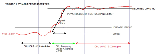
VID denotes applied VCore while VCC denotes the real-time voltage level; these are not to exact scale and are for illustrative purposes only.
The hold period of SpeedStep together with current and power load sensing by the processor allows VCC to settle before the maximum clock multiplier is enforced while VID tolerances remain observed. Voltage excursions that are drastically above or below VID not only can breach processor warranty tolerances with voltage spikes, but also give rise to increased power supply settling times as the PWM circuit feedback loop reacts to the initial power delivery error. During any form of oscillation, the power supply bandwidth is compromised for a small period of time at the resonating frequency. Ultimately, this increase in power line settling time can result in system instability and bring about the shortening of component lifespan. This is the exact reason that Intel set forth design tolerance margins that have to be observed to satisfy stock operation. It is up to the board manufacturers to include and satisfy these safety margins according to the capabilities of the circuits they choose.
Running a board with "no VDroop" under these types of condition may not only violate VID delivery guidelines but can also make the system unstable. Most PWM controllers are designed according to VRM 11.1 spec (they have to be at this point). The VDroop function is a pivotal part of the engineering and development process of these controllers, and configuring this function properly on a board maximizes the performance of the controller in question. It is for this reason that disabling VDroop on some boards may actually cause the voltage to rise when the processor goes into a load state. Disabling VDroop essentially changes the way the controller was designed to work. Custom implementations are obviously possible that surpass the Intel specification guidelines by a wide margin; however, VDroop and settling time are still important facets of high speed and high current operation.
In the following scenario (without VDroop), and with SpeedStep disabled, not only must the PWM controller stabilize VCC when the processor enters load state, but it also has to ramp VCore upwards to reach stable VID for the applied processor frequency - a double whammy for the PWM controller and output FETs. The CPU is overclocked and sitting at a static 4GHz speed regardless of idle or load conditions.
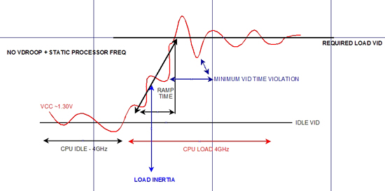
If VCC breaches the minimum processor frequency dependant VID for long enough the result is a system crash. The user will usually counter this effect by adding more voltage so that the idle VID is closer to the required load VID.
Fortunately, not all boards ramp VCC like this with VDroop disabled; if you happen to have one that does, enabling VDroop is not a bad idea at all. In the case of an overclocked processor, real-time software loads that modulate rapidly cause havoc for the PWM controller and FETs, as they fight the inertia of the load change and attempt to raise VID (VCC) while trying to stabilize the load line - not good. Compounding problems further is users seeing voltage fluctuations or a stable voltage as reported by onboard sensors contradicting any of the power delivery guidelines. Unfortunately, these sensing devices are only satisfactory for reporting a crude average voltage value and are nowhere near fast enough to show the real time VCC fluctuations that are occurring in the KHz ~MHz region. Simply put, voltages reported by the BIOS/sensor and software should not be trusted when trying to confirm the presence of voltage spikes on the VCC line.
With all this in mind, we always utilize VDroop for all of our "everyday" overclocking results. On this platform, we do so even when using LN2 cooling as the i7 architecture does not seem to need bucket loads of voltage to reach its full overclocking potential. Suitably engineered boards incorporate VDroop in a manner where VCC sags by around 0.07V under full load even when you apply 1.6V~1.7V in BIOS. So long as you know what the approximate full load VCore is, you can work around it without a problem. In fact, on boards that support dynamic VID changes when the processor is overclocked, we utilize this function for our 24/7 overclocks.
The Classified implementation of SpeedStep and C power states at the time of publication support dynamic VID at stock processor voltage (set to AUTO in BIOS). Once you move past the AUTO value for VCore, VID will remain at the BIOS applied voltage without changing dynamically at idle or load states. That means you don't quite get the IDLE VCore reduction when the processor is overclocked using any other voltage apart from AUTO in the BIOS. This is one of the compromises in having a board designed to push components as far as they will go by using a PWM controller geared for high current delivery far beyond stock speeds.
The 10-phase Volterra solution seems more than qualified to handle an overclocked Nehalem CPU's slew rate demands with its freakish over-engineered specifications. Using the "without VDroop" function on this board does not result in VID being raised during load conditions. However, for the sake of best power delivery and system stability, we still recommend you use VDroop for the best overclocking potential. No matter how good a controller is, VDroop will always help deliver the most stable power to the CPU.


22 Comments
View All Comments
JarredWalton - Friday, February 27, 2009 - link
I'm not even sure that's the target market. More likely this is just a dog and pony show that EVGA will give to the top overclockers of the world, who will also get free CPUs from Intel, RAM from memory companies, etc. Then they will take all of that and push their system to new levels of performance and overclocking. The net result is that they hope having their top motherboard in the fastest systems in the world will have a trickle down effect and people will assume that their lower end products are also the "best". Honestly, it's mostly marketing if you ask me. EVGA might only make 500-1000 of these boards and call it quits for all we know.Jedi2155 - Friday, February 27, 2009 - link
Amen to that Soul.