Jasper Is Here: A Look at the New Xbox 360
by Anand Lal Shimpi on December 10, 2008 12:00 AM EST- Posted in
- Smartphones
- Mobile
Confirming Your Jasper
If you can physically open the box, there's another way of confirming that you have a Jasper without even opening the plastic bag that the console comes in: look at the power connector on the Xbox 360 itself. Each Xbox 360 generation has a power connector that's keyed differently so you can't use a lower powered power supply on a console that requires more power. Now all Xbox 360 power supplies will work on newer consoles, but you can't use newer power supplies on older consoles. Make sense? Let me explain:
The first Xbox 360 (Xenon) needs a 203W power supply. Falcon needs a 175W power supply but can also work with the 203W unit (it just doesn't need to draw that much power so the 203W unit is overkill, but it'll work). Jasper needs 150W but can work with a 203W and a 175W. In other words, the Xbox 360 power supplies are forwards but not backwards compatible.
If you get a Jasper it's not guaranteed that you'll get a 150W power supply, Microsoft still has a lot of Falcons and Falcon-parts in its distribution system so some Jaspers have been sighted with 175W power supplies. If you end up with a 175W unit it's not a big deal, it's going to be slightly less efficient than the 150W unit and your system may end up drawing an extra few watts but it's not a big deal at all - you'll still be far cooler/more power efficient than a Falcon (and possibly be red-ring-free).
To prevent an under powered power supply from being used in the wrong Xbox, Microsoft keyed each of the three Xbox 360 generations differently. The chart below explains it all:
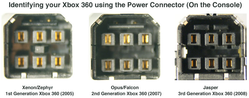
If you see one flat bar on top and a square peg in the middle of the power connector on the console itself you've got a 1st generation Xenon or Zephyr board, these machines use 90nm CPUs and GPUs. If you've just got a flat bar on top with no square peg in the middle, you've got a 2nd generation Opus or Falcon board, these things use 65nm CPUs and 80nm GPUs. Finally if you've got a flat bar split in two on top with no square peg you've got a Jasper, that's a board with a 65nm CPU and a 65nm GPU.


84 Comments
View All Comments
kilkennycat - Wednesday, December 10, 2008 - link
Yep, and for the latest classic example, consider the PC port of GTA4. This port hold the all-time (so far) rotten-banana-prize for the worst console to PC port of a major video-game. Besides the DRM and gross game-play/graphics bugs, the game REQUIRES at least 3 CPU-cores for optimum performance. Code obviously ported over from the 3-core Xbox360 version, with zero optimization for a fewer number of far more capable PC CPU cores. The cartoon-type graphics puts little stress on the GPU. Hopefully, Anandtech in one of the occasional PC game-related articles will lacerate Rockstar and Take Two for this lazily-awful port to the PC.seriouscat - Wednesday, December 10, 2008 - link
Comon AT! Wheres the temperature benchmarks? This was the single most interesting test I was looking foward to after all these months and what do I read? Nothing!Pirks - Wednesday, December 10, 2008 - link
Otherwise he wouldn't write "I'm actually a bit surprised that we haven't seen more focus on delivering incredible visuals on PC games given the existing performance gap" because the answer to that has been printed in media many times, and here it is posted on DailyTech this morning: http://www.dailytech.com/article.aspx?newsid=13648">http://www.dailytech.com/article.aspx?newsid=13648See Anand, it's really easy to make you stop feeling surprised. You won't ever now, will ya? Just remember this P-word, always remember it.
Gunbuster - Wednesday, December 10, 2008 - link
"Most lead-free replacements for conventional Sn60/Pb40 and Sn63/Pb37 solder have melting points from 5–20 °C higher"You need to back up your facts in this one boys.
Staples - Wednesday, December 10, 2008 - link
I have yet to see someone hook up a Jasper to a current meter to test out how much power the darn thing draws.I hope this does cure the RROD because my launch system (Xenon) and the Falcon I bought a year ago both have gone bad. The Falcon used much less power but if the GPU was the real cause of the RROD like many speculate, then hopefully this die shrink takes care of it.
And for all of those who do not know which version you have, do what I do. I have never once looked into the console with a flashlight. I have a kill a watt meter and by comparing anand's numbers to that of your own will narrow down the generation of Xbox you have.
ss284 - Wednesday, December 10, 2008 - link
Power(W) = current(A) * voltage(V).I'm assuming you can do the math. The killawatt is in essence a volt/current meter.
sprockkets - Wednesday, December 10, 2008 - link
Close. Watts is energy. Watts over time is power, or kWh.ahmshaegar - Wednesday, December 10, 2008 - link
Wow. Can't believe I just saw someone post that.The watt is definitely a unit of power. Power is the rate at which you use energy. 1 W = 1 J/s. So the kWh is actually a unit of energy, since you multiply the watt with the hour (a unit of time), which is very odd* if you think about it (1 W = 1 J/s, so 1 kWh is 1000 Wh, or 1000 (J/s)h.
Because 1 hour contains 3600 seconds, 1 kWh is 1000 joules per second multiplied by 1 hour multiplied by 3600 seconds per hour (this last term converts the 1 hour to seconds, so I can cancel out the seconds.)
You then get 1 kWh = 3600000 J, proving that the kWh is indeed a unit of energy.
*It's one of those odd units if you just think about it, but very useful for the utilities.
adhoc - Wednesday, December 10, 2008 - link
I don't understand the comment about lead-free solder melting at high temperatures...Lead-free solder actually has a HIGHER melting point than leaded solder. Instead of worrying about solder melting at "high temperatures" from chip heat dissipation, I'd be more worried about PCB and component reliabilities due to the initial soldering process. PCB laminates that aren't suited for lead-free/RoHS elevated temperatures can warp and/or delaminate, creating immediate or possibly latent failures.
Aside from the PCB materials, components need to be characterized for the higher temperatures during the reflow/wave processes. Ceramic capacitors come to mind as a specific issue; the ceramic can crack under high temperatures (especially temperature gradients during hand-soldering), which can eventually create an open circuit, or worse even a short between power planes.
In the end, I'm just dubious of the explanation of lead-free solder as the failure mode. On the ohter hand, it may very well be related to the required higher temperatures during assembly (and thus bad PCBs and/or component failures).
The0ne - Wednesday, December 10, 2008 - link
Some designers don't account for the higher temperatures when they design PCBs. Actually there's quite alot of them around. That and mixing leaded and lead free parts where SMT has a much harder time processing them. In such case, they end up separating the process to lead, lead-free and sometimes even hand solder because of the particular design. Then you have designs that doesn't take into consideration of the distances between components or more specifically between vias. With very fine pitches this can become a nightmare for SMT.