Seasonic M12D 850W: DC-to-DC Perfection?
by Christoph Katzer on November 26, 2008 12:00 AM EST- Posted in
- Cases/Cooling/PSUs
Testing with the Chroma ATE Programmable Load
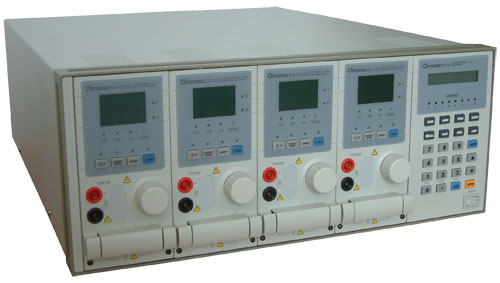
Our test equipment consists of two Chroma programmable DC Loads that enable us to test power supplies with an output of up to 1500W. The biggest advantage of the Chroma DC Loads is simply the high precision it provides. It can measure differences as small as 0.001V and 0.0001A, which will provide us with best-in-class results.
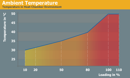
When programming the Chroma with specific amounts of load calculated according to the ATX norm, we are able to load power supplies to an exact percentage. We can now show results at every specific percentage needed. To get the best overview of a power supply, we load each unit with 10%, 20%, 50%, 80%, 100%, and 110% of the specified output. This is easy to calculate for a 1000W power supply: the 10% load is 100W and 110% load is 1100W. Remember that this is the amount of power the PSU delivers; due to inefficiencies, a power supply will actually draw more power from the wall.
Note: If you would like to know more about our testing methodology, equipment, and environment, please read our PSU testing overview.
We have added an additional 10% on the highest load to see how the units perform with overload. This test will be performed in all future reviews. The overload test is performed at room temperature as well as under more stressful conditions; to ensure we are not too cruel to the power supplies, we will keep the ambient temperature at 50°C in the stress test. Experience shows that many units can stand the overload at room temperature but will experience problems with higher temperature and overload together. Only the best-built units will survive this.
The Testing Environment
There is one flaw in testing power supplies with programmable loads while trying to measure the sound pressure levels at the same time. Because the programmable loads get very loud, there is no chance of hearing the power supply on the test stand. In order to make accurate measurements of the noise levels we needed a way to separate the test unit and the programmable loads. Our solution was to build a very thick box around the unit.
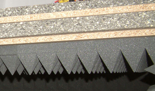
We concluded that a five-layer box with a total thickness of 6" (15cm) containing two layers of wood and three layers of special foam would suffice. It is designed as a box within a box. The inner box does not touch any part of the outer box, making it difficult for acoustic noise to pass through in the form of vibration. Each box is isolated on both sides with a layer of heavy foam that is normally used to insulate engines. On the inside we have an additional layer of 4" (10cm) thick pyramidal foam on every side of the box to eliminate the acoustic waves coming from the test object as well as we can.
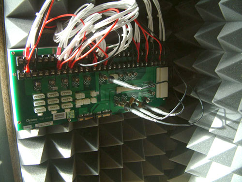
To ensure a completely closed system we installed the printed circuit board that the connectors of the power supply are attached to inside the anechoic room/box. In other box designs, you would need to put all the cables through the wall. Unfortunately, that would result in the inside of the box not being fully isolated anymore. Our design keeps everything that needs to be connected inside of the box and maintains isolation.


45 Comments
View All Comments
mindless1 - Saturday, November 29, 2008 - link
First of all, in a design like this no they don't produce their airflow at a significantly lower RPM. You've fallen victim to dubious free air ratings, and ignored that lower quality fans tend to increase in noise level sooner due to wear.Second, choosing 140mm fan means you can't pick among many of the good fan makes which the Sanyo Denkis are. Let's just leave a good fan alone instead of replacing it with something junky.
Mr Perfect - Wednesday, December 3, 2008 - link
I'm going by fan testing from SPCR, not the manufacturer's fluff specs. From what they've seen, to hit x cfm rate, a 80mm is going to have to spin faster then a similarly built 92mm, while that 92mm is going to rev higher then a 120mm, and presumably any good 120mm is going to be rotating faster then any quality 140mm at the same real CFM.And cheap fans are definitely not what I was suggesting.
emboss - Wednesday, November 26, 2008 - link
Yes, it's me harping on about ripple and noise again :)There appears to be no ripple in the traces you have shown. The "ripple" figures you quoted are actually noise figures. However, I suspect that the ripple is still there, just overwhelmed by the noise. A low-pass filter to cut off anything more than 1 MHz or so would possibly clean it up and allow ripple numbers to be be determined.
Also, the comparison of 12V1 and 12V2 is just a waste of space. They both come from the same place (they just have independent current limiting, that's all).
jabber - Wednesday, November 26, 2008 - link
This is where I see a future for PSU tech. As more people want to create HTPC/Music Servers I think it would be really good to be able to buy PSUs that deliver high quality, stable, filtered, clean power with the minimum of RFI hash etc.Units would only need to be around the 300-400w mark (could probably get away with 250w).
Would be nice to be able to get stripped down motherboards with traces designed to be as short as possible and ultra quality power circuits to go with them with.
mindless1 - Saturday, November 29, 2008 - link
You are entirely misunderstanding the issues. The power supplied to the system is not directly driving anything where the ripple matters. Voltages are stepped down on the mainboard itself which is a separate more local source of noise, IF that noise would've mattered. A decent audio card will have a linear regulation stage and the digital circuits don't care about a minor bit of ripple.IOW, there is no reason to believe it would make a difference.
Also, stripped down motherboards with short traces also has no point. These are digital circuits while you are thinking in terms of crude analog audio where the traces need be short because the designer didn't properly shield or ground-plane the circuits. Within the analog audio circuits on boards, the traces ARE short, as much so as reasonably possible. Even then, it's drifting the wrong direction since we've had digital output for audio.
Bottom line- all you need is a good audio card with digital output. There will be zero difference which board or PSU you choose so long as they otherwise worked fine.
Mr Perfect - Wednesday, November 26, 2008 - link
ROFL. I'm sure that Monster would be all over that market segment. One thousand dollar 400watt power supplies with gold plated connectors, EMI shielding, and "audiophile grade" filtered power.Granted, clean power is what sets the good power supplies apart from the chaff, but as soon as you step into the music realm, the marketing machine rules supreme.
jabber - Thursday, November 27, 2008 - link
Indeed there could be an element of that. However, unlike hifi gear which only gets tested by listening. These components, as they are still PC based would be subject to decent technical testing as per websites such as these.Extravagant claims would soon be put to the test. Unfortunately thats not something that is done quite nearly enough in the audio world.
djc208 - Wednesday, November 26, 2008 - link
Since you've been posting all these great articles on not only PSUs but also energy requirements and effeciency it's really made me look realistically at my system.I picked up a kill-a-watt a few weeks ago and put it on the plugs for my desktop and my server and the numbers I saw completely re-alligned my expectations. Neither of those systems pull over 200W with anything I throw at them. The server isn't high end stuff but has lots of drives spinning and runs 24/7.
The desktop isn't a gaming monster but even plugged into the wall outlet for the UPS I maxed out at about 250W, and that's with the 19" CRT on the same outlet.
So thanks for the education, it's saved me money already. I needed to replace the server PSU and saved money by shopping in the right portion of the spectrum as well as shooting for max efficiency at the wattage I saw vice some bloated "recomendation".
computerfarmer - Wednesday, November 26, 2008 - link
If the 5v and 3.3v draw from the 12V rail(DC to DC) then what does the 40A rating per rail mean? Is this the rating after the draw from the other rails? What is the max amp draw from both 12V rails?The reason for this question came from looking at the specs from "Antec Signature850". See here http://www.antec.com/usa/productDetails.php?lan=us...">http://www.antec.com/usa/productDetails.php?lan=us... This has rail 1&2 at 22A each and Rails 3&4 at 25A each, yet the total is 65A max.
How is anyone supposed to understand these specs?
valdir - Wednesday, November 26, 2008 - link
The ripple measurements need a more severe judgment, since they are higher than, for example, Corsair's TX750 and worst of all, they have a very bad waveform, with very high frequency components.