Cooler Master UCP 900W
by Christoph Katzer on July 29, 2008 3:00 AM EST- Posted in
- Cases/Cooling/PSUs
Testing with the Chroma ATE Programmable Load
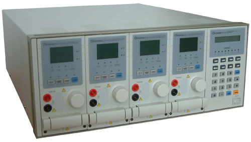
Our test equipment consists of two Chroma programmable DC Loads that enable us to test power supplies with an output of up to 1500W. The biggest advantage of the Chroma DC Loads is simply the high precision it provides. It can measure differences as small as 0.001V and 0.0001A, which will provide us with best-in-class results.
When programming the Chroma with specific amounts of load calculated according to the ATX norm, we are able to load power supplies to an exact percentage. We can now show results at every specific percentage needed. To get the best overview of a power supply, we load each unit with 10%, 20%, 50%, 80%, 100%, and 110% of the specified output. This is easy to calculate for a 1000W power supply: the 10% load is 100W and 110% load is 1100W. Remember that this is the amount of power the PSU delivers; due to inefficiencies, a power supply will actually draw more power from the wall.
Note: If you would like to know more about our testing methodology, equipment, and environment, please read our PSU testing overview.
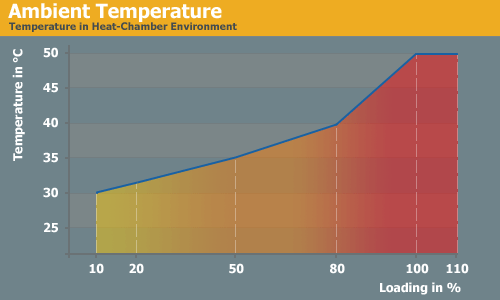
We have added an additional 10% on the highest load to see how the units perform with overload. This test will be performed in all future reviews. The overload test is performed at room temperature as well as under more stressful conditions; to ensure we are not too cruel to the power supplies, we will keep the ambient temperature at 50°C in the stress test. Experience shows that many units can stand the overload at room temperature but will experience problems with higher temperature and overload together. Only the best-built units will survive this.
The Testing Environment
There is one flaw in testing power supplies with programmable loads while trying to measure the sound pressure levels at the same time. Because the programmable loads get very loud, there is no chance of hearing the power supply on the test stand. In order to make accurate measurements of the noise levels we needed a way to separate the test unit and the programmable loads. Our solution was to build a very thick box around the unit.
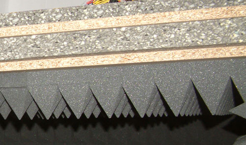
We concluded that a five-layer box with a total thickness of 6" (15cm) containing two layers of wood and three layers of special foam would suffice. It is designed as a box within a box. The inner box does not touch any part of the outer box, making it difficult for acoustic noise to pass through in the form of vibration. Each box is isolated on both sides with a layer of heavy foam that is normally used to insulate engines. On the inside we have an additional layer of 4" (10cm) thick pyramidal foam on every side of the box to eliminate the acoustic waves coming from the test object as well as we can.
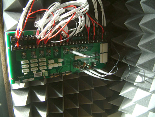
To ensure a completely closed system we installed the printed circuit board that the connectors of the power supply are attached to inside the anechoic room/box. In other box designs, you would need to put all the cables through the wall. Unfortunately, that would result in the inside of the box not being fully isolated anymore. Our design keeps everything that needs to be connected inside of the box and maintains isolation.


33 Comments
View All Comments
MrOblivious - Tuesday, July 29, 2008 - link
Sorry meant to say seems to be indicated in the article in my last line.Adamantine - Tuesday, July 29, 2008 - link
There are four 12v rails, yet you only show regulation on a single rail, not even labeled at that... where are the voltage regulation line graphs for the other 3 rails, if there are in fact 4 rails?jonnyGURU - Tuesday, July 29, 2008 - link
+12V rails are rarely independent. Usually "multiple" +12V rails is just a +12V rail split up into four, six, etc. with an over current protection circuit in place for each. If there's any "regulation" difference between one +12V rail and another, it's usually caused by resistance between the +12V source and the end of the connector and NOT actual poor voltage regulation. So the best course of action would actually be to average out the results or combine +12V rails into one.More on "multiple" +12V rails: http://forums.anandtech.com/messageview.aspx?catid...">http://forums.anandtech.com/messageview.aspx?catid...
Christoph Katzer - Tuesday, July 29, 2008 - link
ehm we combined them into one graph, that's why they are so thick ;) The graph shows in which area all of the rails have been regulated. We had shown differently before but with six rails for example you cant see anything anymore...SilthDraeth - Tuesday, July 29, 2008 - link
I read the review and I saw you nitpick about a few things, but I didn't read about any real problem.JarredWalton - Tuesday, July 29, 2008 - link
The 12V rail problem is that 12V1 (rated at 25A) supplies the power for the 24-pin connector, the 4-pin ATX12V connector, and all the SATA and Molex connectors. Meanwhile, 12V2 *only* powers the EPS12V connector (which quite a few people won't even use!), and 12V3 and 12V4 are dedicated to the PEG connectors.Basically, there's a lot of stuff coming off of the main 12V rail, and thus it's going to be virtually impossible to come anywhere near the rated output unless you happen to have an EPS12V connector on your motherboard. More important is that with the right combination of hardware (i.e. quad-core overclocked CPU, a high-end GPU, and several HDDs) you could easily overload 12V1.
strikeback03 - Wednesday, July 30, 2008 - link
The EPS12V is the 8-pin CPU connector, correct? The same one that seems to be far more common these days on the class of motherboards likely to be used with a 900W PSU than the 4-pin connector?JarredWalton - Wednesday, July 30, 2008 - link
I don't know that I would call EPS12V "common". It's used on some high-end mobos, but not on others. It was initially more of a workstation/server connector. Some PSUs have a 4/8-pin cable that works with either ATX12V or EPS12V, but it seems Cooler Master decided to go with a dedicated ATX12V and a dedicated EPS12V. It would have made a lot more sense IMO if they had all of the peripherals on the same rail as the EPS12V (and ATX12V for that matter).Bozo Galora - Tuesday, July 29, 2008 - link
Weren't you going to add ripple and noise tests?Or do I have the wrong recollection?
These guys say it had 78mv on 12V line
http://www.techpowerup.com/reviews/CoolerMaster/UC...">http://www.techpowerup.com/reviews/CoolerMaster/UC...
Amart - Tuesday, July 29, 2008 - link
Anandtech are not interested in presenting a complete professional review of PSU's, instead they have stated we should "trust them" on ripple and noise questions.I think that Anandtech PSU reviews should look at JonnyGuru.com and HardOcp.com and take notes on how to do things right.