PC Power & Cooling Silencer 750 Quad CF-Edition
by Christoph Katzer on July 18, 2007 1:00 AM EST- Posted in
- Cases/Cooling/PSUs
Internals
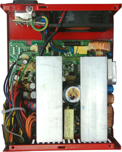
After opening the cover, we are greeted with a simple, clean design. The two big heatsinks stretch across most of the interior. With their size and shape they are well designed for a power supply with an 80mm fan in the back. The air can go through the single fins to cool the interior components. A potential problem with this alignment is the components on the PCB. For example, a transformer directly in the airflow is also blocking the air and creating turbulence.
As seen above, in this particular unit the transformer and capacitor are located in between the two heatsinks. PCP&C didn't put any other important components behind them; thus they will not prevent fresh air from reaching components that need it.
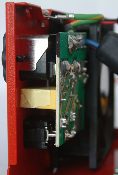
Half of the filtering stage is located on a small PCB directly at the AC-inlet. Power passes through a cable into a fuse and other capacitors before it hits the rectifier bridge.
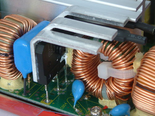
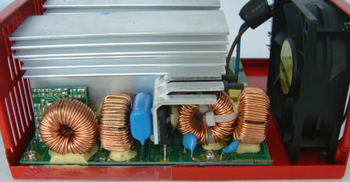
The rectifier bridge is attached to its own small heatsink which cools it down. Some of the fins have a shrinking hose attached to prevent interference with the coil sitting directly below. The coils are only connected through the two cables which makes them pretty unstable. You can see that they are being fixed by cable ties and glue - a common practice.
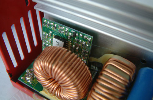
The active PFC is located in the end of the primary side behind a coil. The main-cap is manufactured by Nippon Chemi-Con and normally placed in this area but PCP&C had it moved beside the transformer, and there are no disadvantages in such a design.
After opening the cover, we are greeted with a simple, clean design. The two big heatsinks stretch across most of the interior. With their size and shape they are well designed for a power supply with an 80mm fan in the back. The air can go through the single fins to cool the interior components. A potential problem with this alignment is the components on the PCB. For example, a transformer directly in the airflow is also blocking the air and creating turbulence.
As seen above, in this particular unit the transformer and capacitor are located in between the two heatsinks. PCP&C didn't put any other important components behind them; thus they will not prevent fresh air from reaching components that need it.
Half of the filtering stage is located on a small PCB directly at the AC-inlet. Power passes through a cable into a fuse and other capacitors before it hits the rectifier bridge.
The rectifier bridge is attached to its own small heatsink which cools it down. Some of the fins have a shrinking hose attached to prevent interference with the coil sitting directly below. The coils are only connected through the two cables which makes them pretty unstable. You can see that they are being fixed by cable ties and glue - a common practice.
The active PFC is located in the end of the primary side behind a coil. The main-cap is manufactured by Nippon Chemi-Con and normally placed in this area but PCP&C had it moved beside the transformer, and there are no disadvantages in such a design.


31 Comments
View All Comments
Christoph Katzer - Wednesday, July 18, 2007 - link
Thanks, was of course wrong. I changed it now.