Board Layout and Features
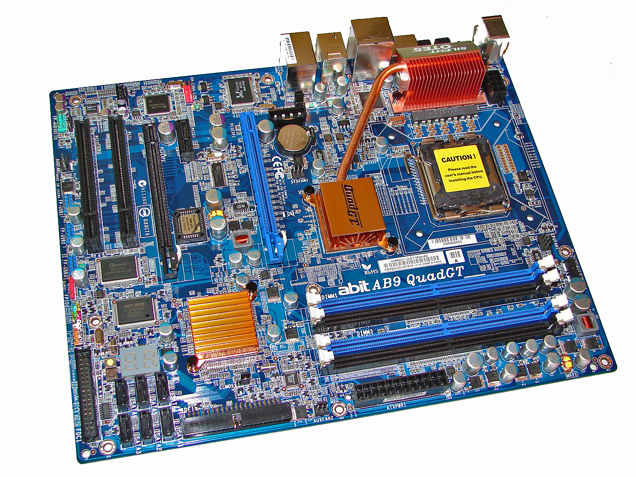
abit really did an excellent job with the layout of this board and the color combination is elegant when compared to some of the more garish schemes we have seen recently on other boards. The board was very easy to install in our Cooler Master CM Stacker 830. Cable management was excellent with our only concern being the location of the floppy drive connector at the bottom of the board. The board features a total of five fan headers that are controlled via µGuru. The board also includes a digital PWM controller and 100% Conductive Polymer Aluminum Solid Capacitors that provided absolutely superb stability throughout testing.
The DIMM module slots' color coordination is correct for dual channel setup based upon the premise of installing DIMMs in the same colored slots for dual-channel operation. It was very easy to install memory modules with a full size video card placed in the top PCI Express x16 slot. abit places the CPU and two auxiliary fan headers above and to the right of the first DIMM slots respectively. The 24-pin ATX power connector is located below the number three and four DIMM slots.
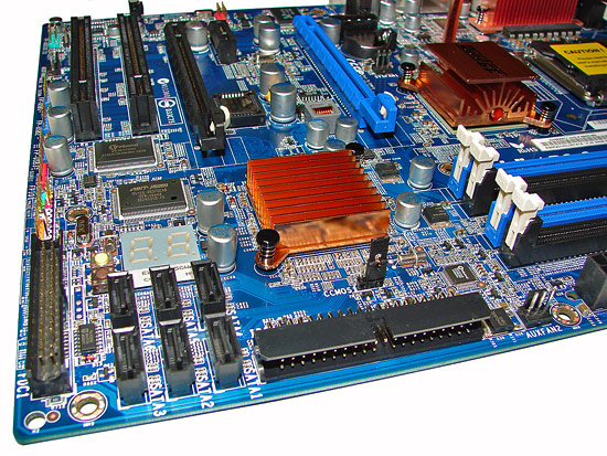
The six Intel ICH8R SATA ports are black and are conveniently located between the IDE and Floppy drive connectors. The SATA ports feature the newer clamp and latch design. We found the positioning of the SATA ports to be very good when utilizing the PCI or second PCI-E x16 physical slot, although we had to bend our SATA cable a little when using the first and second port with our X1950XT video card and we would expect similar issues with other dual-slot GPUs.
The ICH8R is passively cooled and remained cool to the touch throughout testing. abit includes an LED based POST code display and power and reset buttons. The standard clear CMOS jumper is located below the ICH8R chipset with another fan header being located between the IDE and 24-pin ATX connectors. We really would like to see more companies replace the CMOS jumper with a button instead, as it can be very difficult to access the jumper with expansion cards installed, and luckily abit did just that, as we'll see in a moment.
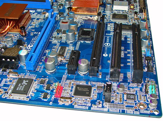
The board comes with one PCI Express x16 connector, one PCI Express x4 (x16 physical), one PCI Express x1, and two PCI 2.3 connectors. The layout of this design offers one of the better dual x16 connector designs we have worked with to date. Only the first PCI slot will be physically unavailable if you use a double slot video card in the second PCI Express x16 physical slot. There is a four-pin 12V Molex connector that is required for dual graphic card operation. We confirmed the PCI Express x4 slot can be used with a wide variety of x1, x2, and x4 cards.
Something else worth noting are the audio features. The black three pin header next to the number two PCI slot and the green front panel audio header is an HDMI Audio header that allows output to a HDMI capable video card. A few HTPC enthusiasts might find that feature to be useful.
Getting back to CPU socket area, we find an excellent amount of room for alternative cooling solutions. We utilized the stock heatsink/fan in our normal testing but also verified a few larger Socket-775 air cooling solutions would fit in this area during our overclocking tests. The Intel P965 MCH chipset is passively cooled with a mid-rise heatsink unit that did not interfere with any installed peripherals and is connected to the digital PWM area via a heat pipe that worked without issue during testing.
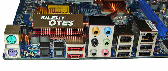
The rear panel contains the standard PS/2 mouse and keyboard ports, LAN port, and 4 USB 2.0 ports. The LAN (RJ-45) port has two LED indicators representing Activity and Speed of the connection through the Realtek Gigabit PCI-E chipset. The audio panel consists of 6 ports that can be configured for 2, 4, 6, and 8-channel audio connections for the Realtek ALC 888 HD codec along with S/PDIF optical out and in ports. The IO panel also features two e-SATA ports, an IEEE 1394 port, and a Clear CMOS switch.
The innovative clear CMOS switch is located next to the PS/2 ports and proved very handy during testing as the BIOS recovery system did not work consistently. With most motherboards lacking parallel and serial ports these days, the I/O panel tends to have quite a bit of unused space, and we would really love to see more companies include a clear CMOS button like this abit board - the only other time we have seen such a button is on several SFF systems.
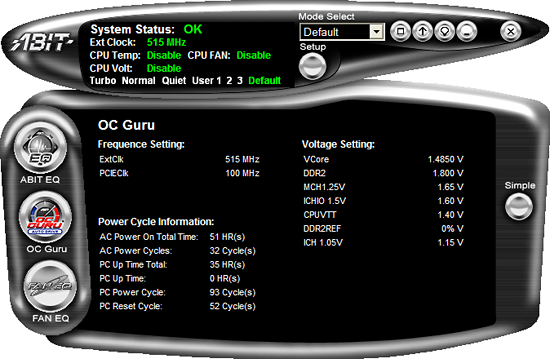
abit includes their µGuru utility which is absolutely the best Windows based software application for overclocking and hardware monitoring... or at least it was until we tried it on this board. Our primary issue is that the memory voltage readings are incorrect and if you change the voltage it will over volt your BIOS settings. We always found the µGuru utility read our memory about .2V to.4V under the BIOS setting. Unfortunately, we fried a pair of Corsair's best 6400C3 1GB modules by increasing the voltage to 2.400V in µGuru which ended up being an actual BIOS setting of 2.7V. Needless to say, our Orthos testing session ended early. Until abit resolves this issue, we strongly advise that you do not use µGuru to change memory voltages. Our testing of the other voltage settings did not reveal any issues, except on occasion the board would lock up if we dropped our CPU core voltage.
 |
| Click to enlarge |
abit really did an excellent job with the layout of this board and the color combination is elegant when compared to some of the more garish schemes we have seen recently on other boards. The board was very easy to install in our Cooler Master CM Stacker 830. Cable management was excellent with our only concern being the location of the floppy drive connector at the bottom of the board. The board features a total of five fan headers that are controlled via µGuru. The board also includes a digital PWM controller and 100% Conductive Polymer Aluminum Solid Capacitors that provided absolutely superb stability throughout testing.
The DIMM module slots' color coordination is correct for dual channel setup based upon the premise of installing DIMMs in the same colored slots for dual-channel operation. It was very easy to install memory modules with a full size video card placed in the top PCI Express x16 slot. abit places the CPU and two auxiliary fan headers above and to the right of the first DIMM slots respectively. The 24-pin ATX power connector is located below the number three and four DIMM slots.
The six Intel ICH8R SATA ports are black and are conveniently located between the IDE and Floppy drive connectors. The SATA ports feature the newer clamp and latch design. We found the positioning of the SATA ports to be very good when utilizing the PCI or second PCI-E x16 physical slot, although we had to bend our SATA cable a little when using the first and second port with our X1950XT video card and we would expect similar issues with other dual-slot GPUs.
The ICH8R is passively cooled and remained cool to the touch throughout testing. abit includes an LED based POST code display and power and reset buttons. The standard clear CMOS jumper is located below the ICH8R chipset with another fan header being located between the IDE and 24-pin ATX connectors. We really would like to see more companies replace the CMOS jumper with a button instead, as it can be very difficult to access the jumper with expansion cards installed, and luckily abit did just that, as we'll see in a moment.
The board comes with one PCI Express x16 connector, one PCI Express x4 (x16 physical), one PCI Express x1, and two PCI 2.3 connectors. The layout of this design offers one of the better dual x16 connector designs we have worked with to date. Only the first PCI slot will be physically unavailable if you use a double slot video card in the second PCI Express x16 physical slot. There is a four-pin 12V Molex connector that is required for dual graphic card operation. We confirmed the PCI Express x4 slot can be used with a wide variety of x1, x2, and x4 cards.
Something else worth noting are the audio features. The black three pin header next to the number two PCI slot and the green front panel audio header is an HDMI Audio header that allows output to a HDMI capable video card. A few HTPC enthusiasts might find that feature to be useful.
 |
| Click to enlarge |
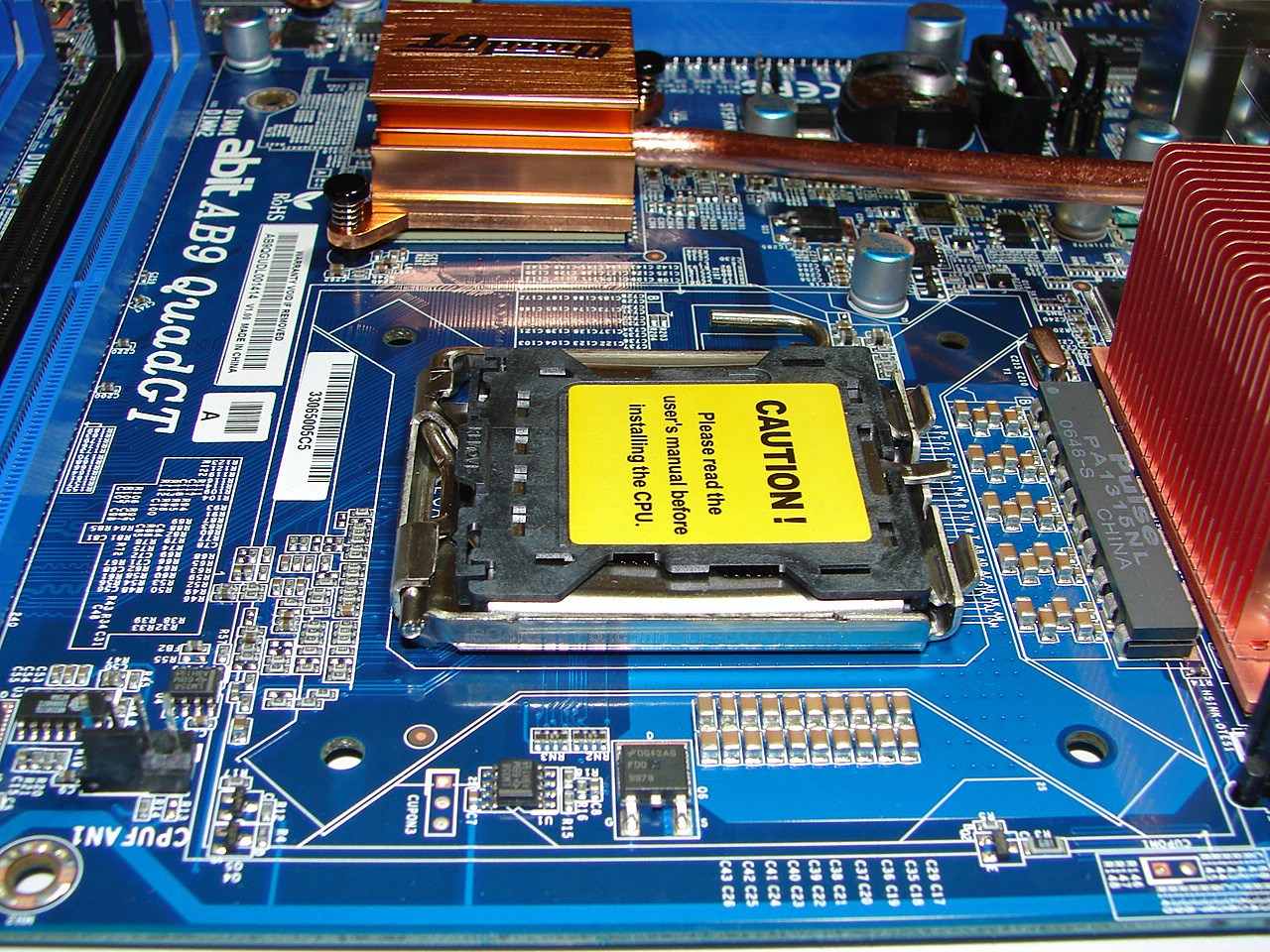
Getting back to CPU socket area, we find an excellent amount of room for alternative cooling solutions. We utilized the stock heatsink/fan in our normal testing but also verified a few larger Socket-775 air cooling solutions would fit in this area during our overclocking tests. The Intel P965 MCH chipset is passively cooled with a mid-rise heatsink unit that did not interfere with any installed peripherals and is connected to the digital PWM area via a heat pipe that worked without issue during testing.
The rear panel contains the standard PS/2 mouse and keyboard ports, LAN port, and 4 USB 2.0 ports. The LAN (RJ-45) port has two LED indicators representing Activity and Speed of the connection through the Realtek Gigabit PCI-E chipset. The audio panel consists of 6 ports that can be configured for 2, 4, 6, and 8-channel audio connections for the Realtek ALC 888 HD codec along with S/PDIF optical out and in ports. The IO panel also features two e-SATA ports, an IEEE 1394 port, and a Clear CMOS switch.
The innovative clear CMOS switch is located next to the PS/2 ports and proved very handy during testing as the BIOS recovery system did not work consistently. With most motherboards lacking parallel and serial ports these days, the I/O panel tends to have quite a bit of unused space, and we would really love to see more companies include a clear CMOS button like this abit board - the only other time we have seen such a button is on several SFF systems.
abit includes their µGuru utility which is absolutely the best Windows based software application for overclocking and hardware monitoring... or at least it was until we tried it on this board. Our primary issue is that the memory voltage readings are incorrect and if you change the voltage it will over volt your BIOS settings. We always found the µGuru utility read our memory about .2V to.4V under the BIOS setting. Unfortunately, we fried a pair of Corsair's best 6400C3 1GB modules by increasing the voltage to 2.400V in µGuru which ended up being an actual BIOS setting of 2.7V. Needless to say, our Orthos testing session ended early. Until abit resolves this issue, we strongly advise that you do not use µGuru to change memory voltages. Our testing of the other voltage settings did not reveal any issues, except on occasion the board would lock up if we dropped our CPU core voltage.


41 Comments
View All Comments
yyrkoon - Monday, January 22, 2007 - link
Oh, Gary, and Jarred, if you're thinking we, your readers are being harsh on you, well perhaps we are to an extent, but speaking for myself, this is because we care, and often look forward to your articles. So think of this as constructive criticism, and not outright flaming, please.Gary Key - Tuesday, January 23, 2007 - link
You are not being harsh. I changed the article back to "Conductive Polymer Aluminum Solid Capacitors" as abit finally confirmed the majority of the capacitors on the board are this type (I looked up the capacitor part numbers before hand but edited the article back the other way). I will update it when they confirm the three capacitors that did not match, they are solid but I have two boards each with different part numbers/suppliers on those three items. At times the manufacturers want us to use their marketing terminology as they might change components during production lot runs based on engineering changes or spot market pricing or to use layman's terms on the website. My previous articles on the Gigabyte boards used the correct terminology based on the capacitors on the board and we had an enormous amount of email and forum traffic asking why we stated something different than on Gigabyte's website at the time. We dumbed it down a little this time after a discussion and should not have. ;) Thanks for the comments and we do listen.yyrkoon - Monday, January 22, 2007 - link
Like the man said, Solid State is used when referring to Integrated Circuits, not Capacitors. The end result, is that you end up 'looking' like a fool, when someone who knows better sees this ( and possibly spread a minor form if 'mis-information).Think about it like this, what is the difference between a NAS, and a SAN ? Would you call a SAN, a NAS, in the company of enterprise IT geeks ? Probably not, at least, not without causing some confusion, or being corrected several times in the process . . .
Operandi - Monday, January 22, 2007 - link
Well they (caps suitable for motherbards) are either AL electrolyte or solid polymer based.Electrolyte caps are the more common type an actually contain electrolytic fluid which can leak when the cap fails. Polymer caps avoid that problem and also last longer -- to the laymen that would be the key difference.
Gary Key - Monday, January 22, 2007 - link
I have used the terminology, "Conductive Polymer Aluminum Solid Capacitors" in past articles and received several emails asking why we do not use what the manufacturers state on their websites as that term was deemed confusing. :)Stele - Monday, January 22, 2007 - link
Part of the problem lies in the confusion about the various kinds of capacitors of that category.Amongst the kind that we're concerned with on motherboards, graphics cards etc, we have the most basic: the aluminium electrolytic capacitor. Because this type started out with liquid electrolyte, the word "liquid" is generally omitted from the name as it is understood.
Then came the solid aluminium electrolytic capacitor, which replaced the liquid electrolyte with, well, a solid one - usually based on aluminium oxide. These are the type that we're nowadays excited about - the lack of liquid makes them more resistant to blow-outs and electrolyte leakage/dry-out, especially under prolonged, high temperature use. For short, they're sometimes referred to as merely "solid electrolytic" ("aluminium" is sometimes left out because, as noted above, the solid electrolyte is usually based on aluminium oxide and hence is understood as such) capacitors. To call them "solid capacitors" isn't totally useful because most capacitors are indeed solid objects :)
In conductive polymer capacitors, on the other hand, the dielectric is made from polymer foil (e.g. polypropylene, polyester, polystyrene, polycarbonate) coated with a layer of metal deposited on the surface. It follows that the basic conductive polymer capacitor has no liquid electrolyte inside - indeed there is no electroylte as the dielectric is purely the polymer foil.
However, manufacturers can and do mix in aluminium electrolyte with the polymer foil to improve certain performance characteristics; the electrolyte is often solid (rather than liquid) aluminium-based, hence "conductive polymer aluminium solid electrolytic capacitor".
As such, the exact names can mean quite distinct types of capacitors, and are not merely loose permutations of words like "electrolytic", "aluminium", "solid" and "polymer"... so if one wants to accurately describe a capacitor being used, one would need to double-check exactly what dielectric is being used in that capacitor :)
Marlin1975 - Monday, January 22, 2007 - link
Thats a understatement. The only thing i don't like about my 965 board is lack of IDE and the use of the jmicron junk.
One of the reasons I am waiting for more 650i boards and the ?last? ati chipset for Intel chips.
LoneWolf15 - Monday, January 22, 2007 - link
It's one of the reasons I'd still chose i975x rather than i965 for a chipset. i975X still has native Intel IDE.Due to recent nVidia chipset/board issues, and past issues with heat production, I'm not sure I'd choose them for an Intel board either, so that leaves the i975X as the only chipset I'd be comfortable with.
Numb3rs - Thursday, January 25, 2007 - link
Honestly, what in a new build would require and IDE interface..? eSATA is important and I am glad it's included. Abit has always made mobos dropping legacy devices no longer used by enthusiasts. Look at their old Abit "MAX" boards.
Why, in 2007 are manufacturers still using serial and parrallel I/O's..? Remove them completly and free the backplane for more useful eSATA, USB..etc
LoneWolf15 - Friday, January 26, 2007 - link
Obviously, you've never configured a Cisco router through its console port (which usually requires a serial port). And perhaps I don't want my list of optical drives confined to only SATA (currently Plextor and LiteOn are my only options, and I don't want one due to price and the other due to writing quality reasons).There are also some known issues with using Symantec Ghost on the JMicron chipset. Unless I hear they are worked out, that's an important thing to me too, and so IDE is still important to me. Just because it isn't useful to you doesn't mean it isn't to a lot of others.