Intel P965: Mid-Range Performance Sector Roundup
by Gary Key on October 20, 2006 9:00 PM EST- Posted in
- Motherboards
Biostar TForce P965 Deluxe: Board Layout and Features
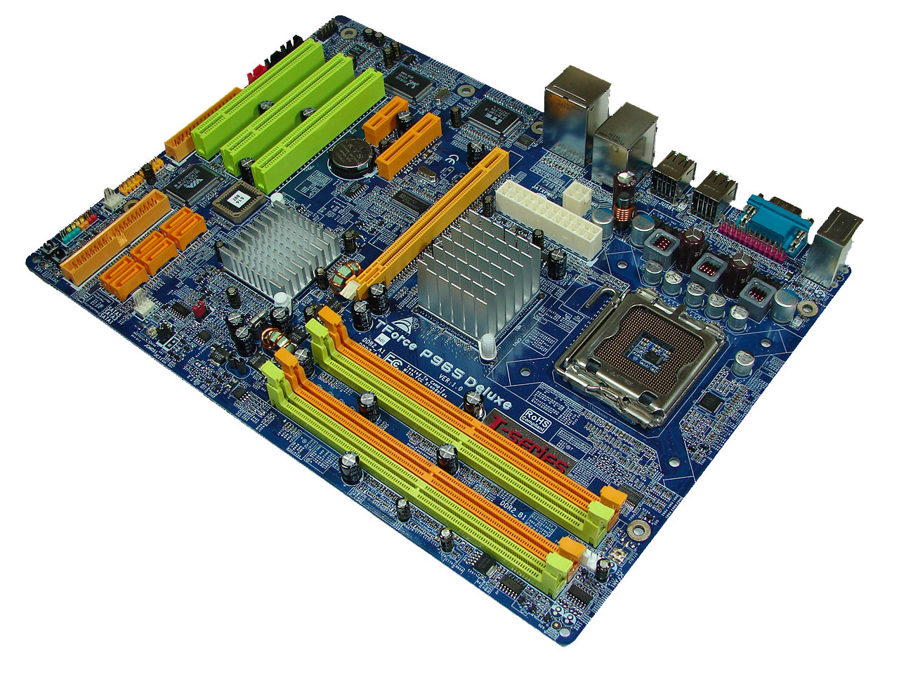
Biostar designed a well laid out board with an interesting color combination that grabs your attention without being overly aggressive. The board was extremely easy to install in our Cooler Master CM Stacker 830 case with all connections easily reached. However, the location of the 24-pin and 4-pin ATX connectors near the CPU area could cause cable management issues with larger air coolers like the Scythe Infinity. We also recommend installing the 4-pin ATX connector first as it is difficult to attach it with the 24-pin cable already installed. Biostar includes three fan headers although we wish there was an additional fan header near the I/O panel. The board features a three-phase voltage regulator system that provided excellent stability throughout our testing.
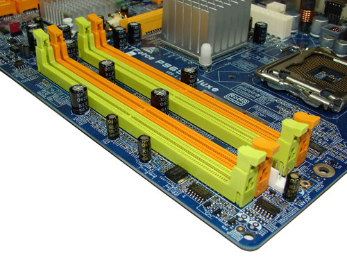
The DIMM module slots' color coordination is correct for dual channel setup based upon the premise of installing DIMMs in the same colored slots for dual-channel operation. It is nearly impossible to install memory modules with a full size video card placed in the PCI Express x16 slot. Biostar places the CPU fan header in between the number two and three memory module and it is a fair distance to reach for most CPU fan/heatsink cables. The board features a total of three fan headers. A fourth one would have been preferred near the I/O panel.
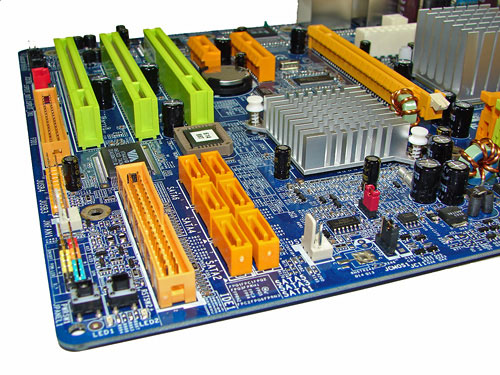
The six Intel ICH8R SATA ports are orange and are conveniently located to the left of the ICH8R Southbridge and second fan header. The SATA ports feature the newer clamp and latch design. We found the positioning of the SATA ports to be very good when utilizing the PCI 2.3 slots. The ICH8R is passively cooled and remained cool to the touch throughout testing.
The clear CMOS jumper is color coded black and is located in an easy access location at the edge of the board near the second fan header. Biostar includes a power on and reset button at the bottom corner of the board next to the VIA IDE connector. The chassis panel, third fan header, and USB connectors are located along the left edge of the board.
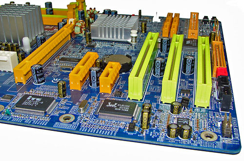
The board comes with (1) physical PCI Express x16 connector, (1) PCI Express x4, (1) PCI Express x1, and (3) PCI 2.3 connectors. The layout of this design offers one of the best single x16 connector designs we have worked with as none of the slots are blocked when using a dual slot video card in the x16 slot. We have to give credit to Biostar for this impressive layout and combination of slots on a mid-range board. However, the sacrifice for this layout is the inability to change memory modules with most video cards installed. The floppy drive connector is located at the edge of the board next to the last PCI slot. We would just as well have this connector disappear at this time.
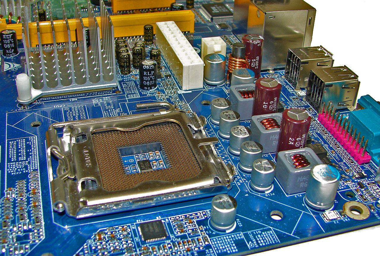
Getting back to CPU socket area, we find a fair amount of room for alternative cooling solutions. We utilized the stock heatsink/fan in our normal testing but also verified a few larger Socket-775 air cooling solutions would fit in this area during our overclocking tests. The Intel P965 MCH chipset is passively cooled with a mid-rise heatsink unit that did not interfere with any installed peripherals. However, it was very difficult routing the ATX power cables to their connectors with a cooling solution like the Tuniq Tower 120 installed. Fortunately our power supply had cables that were sleeved that allowed us to bend the cables around the heatsink area without worry about ripping a wire open.
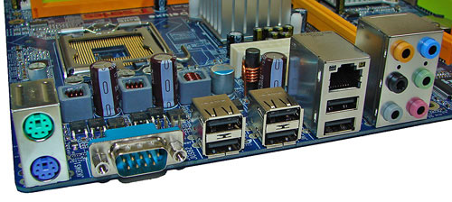
The rear panel contains the PS/2 mouse and keyboard ports, LAN port, and 6 USB 2.0 ports. The LAN (RJ-45) port has two LED indicators representing Activity and Speed of the connection through the Realtek RTL8110SC Gigabit PCI-E chipset. The audio panel consists of 6 ports that can be configured for 2, 4, 6, and 8-channel audio connections for the Realtek ALC 883 HD codec. The panel also has a serial port and we would have preferred a S/PDIF optical out port to have been included in this area.
 |
| Click to enlarge |
Biostar designed a well laid out board with an interesting color combination that grabs your attention without being overly aggressive. The board was extremely easy to install in our Cooler Master CM Stacker 830 case with all connections easily reached. However, the location of the 24-pin and 4-pin ATX connectors near the CPU area could cause cable management issues with larger air coolers like the Scythe Infinity. We also recommend installing the 4-pin ATX connector first as it is difficult to attach it with the 24-pin cable already installed. Biostar includes three fan headers although we wish there was an additional fan header near the I/O panel. The board features a three-phase voltage regulator system that provided excellent stability throughout our testing.
The DIMM module slots' color coordination is correct for dual channel setup based upon the premise of installing DIMMs in the same colored slots for dual-channel operation. It is nearly impossible to install memory modules with a full size video card placed in the PCI Express x16 slot. Biostar places the CPU fan header in between the number two and three memory module and it is a fair distance to reach for most CPU fan/heatsink cables. The board features a total of three fan headers. A fourth one would have been preferred near the I/O panel.
The six Intel ICH8R SATA ports are orange and are conveniently located to the left of the ICH8R Southbridge and second fan header. The SATA ports feature the newer clamp and latch design. We found the positioning of the SATA ports to be very good when utilizing the PCI 2.3 slots. The ICH8R is passively cooled and remained cool to the touch throughout testing.
The clear CMOS jumper is color coded black and is located in an easy access location at the edge of the board near the second fan header. Biostar includes a power on and reset button at the bottom corner of the board next to the VIA IDE connector. The chassis panel, third fan header, and USB connectors are located along the left edge of the board.
The board comes with (1) physical PCI Express x16 connector, (1) PCI Express x4, (1) PCI Express x1, and (3) PCI 2.3 connectors. The layout of this design offers one of the best single x16 connector designs we have worked with as none of the slots are blocked when using a dual slot video card in the x16 slot. We have to give credit to Biostar for this impressive layout and combination of slots on a mid-range board. However, the sacrifice for this layout is the inability to change memory modules with most video cards installed. The floppy drive connector is located at the edge of the board next to the last PCI slot. We would just as well have this connector disappear at this time.
 |
| Click to enlarge |
Getting back to CPU socket area, we find a fair amount of room for alternative cooling solutions. We utilized the stock heatsink/fan in our normal testing but also verified a few larger Socket-775 air cooling solutions would fit in this area during our overclocking tests. The Intel P965 MCH chipset is passively cooled with a mid-rise heatsink unit that did not interfere with any installed peripherals. However, it was very difficult routing the ATX power cables to their connectors with a cooling solution like the Tuniq Tower 120 installed. Fortunately our power supply had cables that were sleeved that allowed us to bend the cables around the heatsink area without worry about ripping a wire open.
The rear panel contains the PS/2 mouse and keyboard ports, LAN port, and 6 USB 2.0 ports. The LAN (RJ-45) port has two LED indicators representing Activity and Speed of the connection through the Realtek RTL8110SC Gigabit PCI-E chipset. The audio panel consists of 6 ports that can be configured for 2, 4, 6, and 8-channel audio connections for the Realtek ALC 883 HD codec. The panel also has a serial port and we would have preferred a S/PDIF optical out port to have been included in this area.


62 Comments
View All Comments
smn198 - Monday, October 23, 2006 - link
Would you be able to re-run using 4 drives for all of the tests please?
jonp - Sunday, October 22, 2006 - link
-- “…budget sector and includes boards from ECS, Foxconn, Intel, and Gigabyte.” – will the MSI P965 Neo-F be in this set?-- the Abit AB9 Pro feature set does not show the eSata port on the SI 3132 (two SATA). it does show a serial port on the i/o panel but not one in the picture.
-- The Biostar feature set shows 4 USB on the i/o panel when there are six in the picture.
JarredWalton - Sunday, October 22, 2006 - link
Fixed - thanks.powchi - Saturday, October 21, 2006 - link
Can I use a 20-pin power supply on these boards since all are using 24-pin connectors? Or will I be needing 20pin to 24pin adaptor?The PSU is an Enermax NoiseTaker EG475P-VE SFMA 470W ATX 12V v1.3.
Aikouka - Sunday, October 22, 2006 - link
Some motherboard manufacturers will no longer support your motherboard if they find out you've been running it with a 20-pin ATX plug or a 20->24-pin adapter. Just be safe and get a newer PSU :). I know DFI will no longer support the motherboard if it specifically asks for a 24-pin.JarredWalton - Saturday, October 21, 2006 - link
Technically, yes you can use 20-pin PSUs. Will they work, and will the system be stable? That varies. I haven't had any issues on the systems where I've done it, but if you do high overclocking it will likely become a serious issue.powchi - Saturday, October 21, 2006 - link
Jarred,So there's no need to use a 20pin to 24pin adaptor? What are the differences when using and not using an adaptor? Thanks.
lopri - Sunday, October 22, 2006 - link
No. As a matter of fact, the adapter should be avoided. Just plug the 20-pin connector to 24-pin receptacle with 4-pin left empty. Like Jarred said, it should work in theory and it does in practice. However, the quality of PSU and how intense is one's OC can affect the (long-term) stability.JarredWalton - Sunday, October 22, 2006 - link
I suppose the adapter *could* help, as it ensures power is available on all the 24-pins, but you're still taking the power from the same source so depending on how that works out it can actually make things worse. I would typically say that if you have a 400W or better PSU you should be fine with little to moderate OC'ing even with 20-pins. (I have an OCZ ModStream 450W that certainly works fine in a 939 board with a decent 2.0 to 2.6 GHz overclock.)lopri - Sunday, October 22, 2006 - link
Yes! Not to brag about myself or anything, but I went through countless Socket 939 Opterons on DFI NF4 SLI-D with original Antec TruePower EPS12V (20-pins, not the TP2 with 24-pins) including an Opteron 165 @3.0GHz (9x333). TCCD up to 325MHz/2.5-4-3-8! The setup was absolutely stable.