Foxconn and Gigabyte Tackle Socket AM2
by Jarred Walton on June 22, 2006 1:30 AM EST- Posted in
- Motherboards
Gigabyte: Board Layout
Gigabyte is a name that almost everyone has heard of when it comes to motherboards. They are a tier 1 manufacturer, and they are often one of the first to market with products for a new platform. Gigabyte has also been one of the pioneers in the extreme enthusiast market, with motherboards offering dual BIOS chips in order to recover from failed flash attempts, improved voltage regulation, and innovative cooling solutions. They sent us a prerelease sample of their latest nForce 590 SLI motherboard for testing, which is currently positioned as their top AM2 offering.
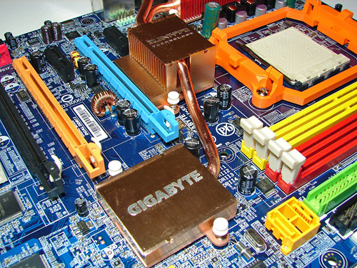
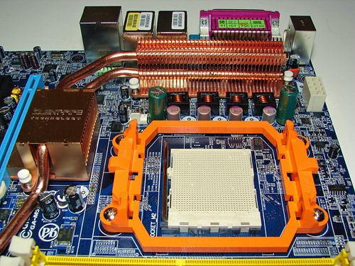
One of the first things that you immediately notice on this motherboard is the impressive cooling solution. Heatsinks connected by heatpipes are used to cool the Northbridge, Southbridge, and some of the voltage regulation chips. What's particularly impressive is the fact that all of the cooling is done without any fans, making for what should be a completely silent motherboard in the right configuration.
The layout as a whole is near perfect, with every connection in an easy to reach location. The ATX power connectors, both 24-pin and 8-pin, are located on the board edges in places that can be reached without interfering with system airflow. As with the Foxconn motherboard, the 4-pin auxiliary power Molex connector is located at the bottom of the board, but that's about the only potentially difficult to reach location, and this position is commonly used on other motherboards as well so we can't complain too much.
Feelings on the appearance and color scheme of the motherboard are of course up for individual interpretation, but Gigabyte sticks with their traditional blue PCB and brightly colored connectors. Depending on your preference, this may be either attractive or garish. If you're planning on placing the motherboard in a case with a window and UV lighting, you probably like the design. For most other people, it's a minor concern, and as long as everything functions well it doesn't matter too much what color the motherboard is.
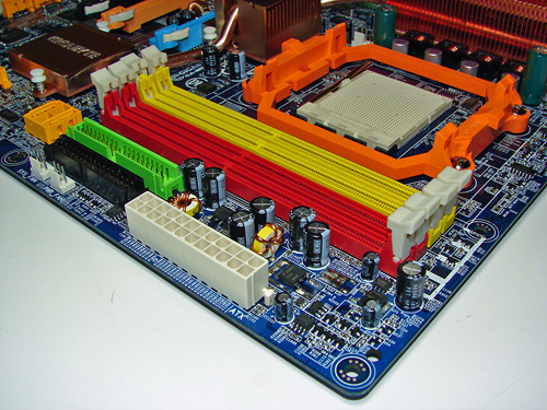
The memory slots are red and yellow, and are properly color-coded for dual channel operation. However, we prefer the configuration of the Foxconn motherboard, which allows you to run with two DIMMs while still having a gap between the memory modules. If you plan to install four DIMMs, it won't matter, and probably more important is that the color coding makes sense. A few manufacturers still seem to think that the slots of each memory channel should be the same color, but the majority of users will assume that you should install two DIMMs into the same colored slots. That seems more logical to us, and we would encourage other manufacturers to follow that color coding style.
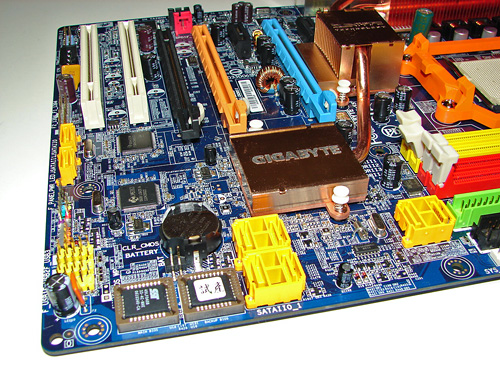
We mentioned before that Gigabyte uses the new clamp and latch SATA connectors, and you can see those in this image of the bottom right corner of the motherboard. Somewhat interesting to note is that this is the first motherboard with clamp and latch connections I've used that actually includes the appropriate clamp and latch cables. Why include the new style connector if you don't include the appropriate cables, right? The bottom two SATA ports are powered by a J-Micro chip. Also included is an eSATA bracket, along with external power, which can be convenient if you ever want to run a hard drive outside of your case. While two eSATA ports are on the bracket, the included external power cable we received only supports one hard drive. Since we are testing a prerelease motherboard, the complete accessory package was not included, so hopefully a power cable for two hard drives will ship with the retail motherboards.
You can also see the Texas Instruments FireWire controller directly below the Southbridge, used to support up to three FireWire ports - one 4-pin connector on the rear bracket, as well as headers for two additional ports. Considering that Gigabyte was the first company to offer 1394b FireWire support on their motherboards, it's somewhat interesting to see that they are using what is generally considered an inferior FireWire chip these days. The FireWire headers are to the left of the bottom SATA ports. Just right of the same SATA ports, you can see the front panel connector block, and to the right of that are the three internal USB headers.
Checking out the rear panel, Gigabyte has chosen to go with a more traditional configuration. You get two LAN ports, four USB ports, six audio jacks, one serial port, one parallel port, the previously mentioned mini FireWire 1394a port, S/PDIF out, and the standard PS/2 keyboard and mouse connectors. All the space on the back panel is put to good use, and while opinions differ as to whether or not parallel and serial ports should still be included, it's at least good to have variety of options in this area among the manufacturers. If you still have an old parallel-port printer that you don't want to upgrade, or any other peripheral that uses one of these ports, then you probably really want the ports. Others might have preferred more USB ports on the rear panel. However, an expansion bracket is included that supports four more USB ports. This uses two of the three USB headers on the motherboard, so you still have one header remaining for any front-panel USB ports.
So what's missing from the Gigabyte board? You don't get onboard reset and power switches (or a small speaker), and some people might have preferred 1394b FireWire. Really, though, there's very little that's wrong with the design of this motherboard. We could nitpick a few areas, but in order to add any more features we would have to give up other features. Do you want the third PCI slot, or should we keep the extra X16 PCI-E slot? We would say Gigabyte made the right choice there, and the only real question that remains is: how does the board perform?
Gigabyte is a name that almost everyone has heard of when it comes to motherboards. They are a tier 1 manufacturer, and they are often one of the first to market with products for a new platform. Gigabyte has also been one of the pioneers in the extreme enthusiast market, with motherboards offering dual BIOS chips in order to recover from failed flash attempts, improved voltage regulation, and innovative cooling solutions. They sent us a prerelease sample of their latest nForce 590 SLI motherboard for testing, which is currently positioned as their top AM2 offering.
 |
| Click to enlarge |
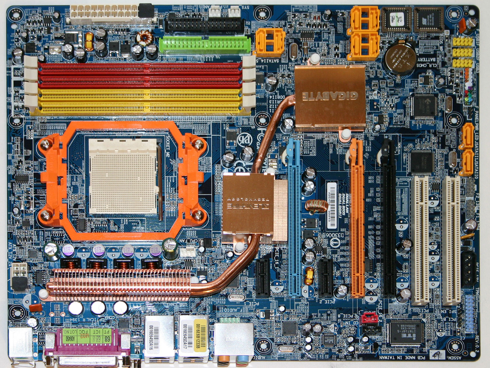
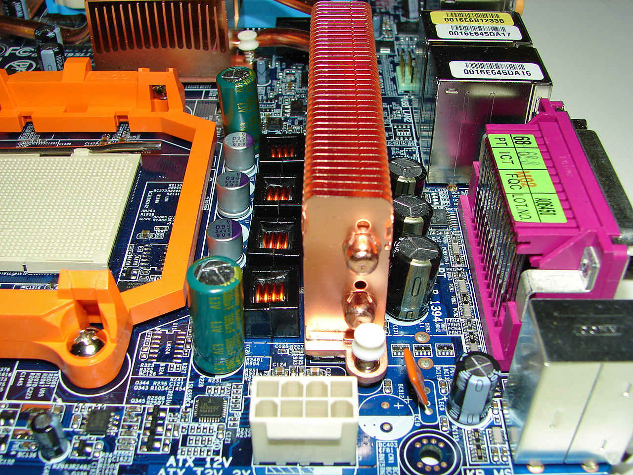
One of the first things that you immediately notice on this motherboard is the impressive cooling solution. Heatsinks connected by heatpipes are used to cool the Northbridge, Southbridge, and some of the voltage regulation chips. What's particularly impressive is the fact that all of the cooling is done without any fans, making for what should be a completely silent motherboard in the right configuration.
The layout as a whole is near perfect, with every connection in an easy to reach location. The ATX power connectors, both 24-pin and 8-pin, are located on the board edges in places that can be reached without interfering with system airflow. As with the Foxconn motherboard, the 4-pin auxiliary power Molex connector is located at the bottom of the board, but that's about the only potentially difficult to reach location, and this position is commonly used on other motherboards as well so we can't complain too much.
Feelings on the appearance and color scheme of the motherboard are of course up for individual interpretation, but Gigabyte sticks with their traditional blue PCB and brightly colored connectors. Depending on your preference, this may be either attractive or garish. If you're planning on placing the motherboard in a case with a window and UV lighting, you probably like the design. For most other people, it's a minor concern, and as long as everything functions well it doesn't matter too much what color the motherboard is.
The memory slots are red and yellow, and are properly color-coded for dual channel operation. However, we prefer the configuration of the Foxconn motherboard, which allows you to run with two DIMMs while still having a gap between the memory modules. If you plan to install four DIMMs, it won't matter, and probably more important is that the color coding makes sense. A few manufacturers still seem to think that the slots of each memory channel should be the same color, but the majority of users will assume that you should install two DIMMs into the same colored slots. That seems more logical to us, and we would encourage other manufacturers to follow that color coding style.
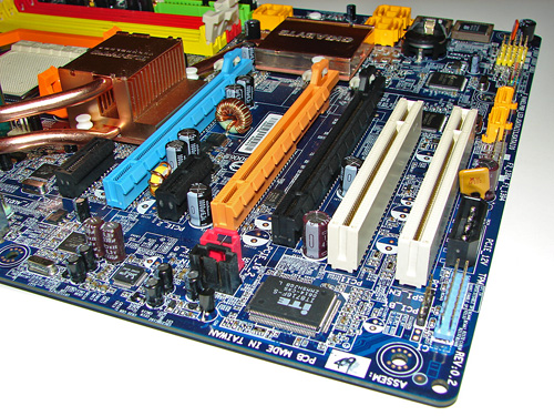
We mentioned before that Gigabyte uses the new clamp and latch SATA connectors, and you can see those in this image of the bottom right corner of the motherboard. Somewhat interesting to note is that this is the first motherboard with clamp and latch connections I've used that actually includes the appropriate clamp and latch cables. Why include the new style connector if you don't include the appropriate cables, right? The bottom two SATA ports are powered by a J-Micro chip. Also included is an eSATA bracket, along with external power, which can be convenient if you ever want to run a hard drive outside of your case. While two eSATA ports are on the bracket, the included external power cable we received only supports one hard drive. Since we are testing a prerelease motherboard, the complete accessory package was not included, so hopefully a power cable for two hard drives will ship with the retail motherboards.
You can also see the Texas Instruments FireWire controller directly below the Southbridge, used to support up to three FireWire ports - one 4-pin connector on the rear bracket, as well as headers for two additional ports. Considering that Gigabyte was the first company to offer 1394b FireWire support on their motherboards, it's somewhat interesting to see that they are using what is generally considered an inferior FireWire chip these days. The FireWire headers are to the left of the bottom SATA ports. Just right of the same SATA ports, you can see the front panel connector block, and to the right of that are the three internal USB headers.
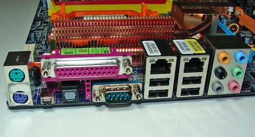
Checking out the rear panel, Gigabyte has chosen to go with a more traditional configuration. You get two LAN ports, four USB ports, six audio jacks, one serial port, one parallel port, the previously mentioned mini FireWire 1394a port, S/PDIF out, and the standard PS/2 keyboard and mouse connectors. All the space on the back panel is put to good use, and while opinions differ as to whether or not parallel and serial ports should still be included, it's at least good to have variety of options in this area among the manufacturers. If you still have an old parallel-port printer that you don't want to upgrade, or any other peripheral that uses one of these ports, then you probably really want the ports. Others might have preferred more USB ports on the rear panel. However, an expansion bracket is included that supports four more USB ports. This uses two of the three USB headers on the motherboard, so you still have one header remaining for any front-panel USB ports.
 |
| Click to enlarge |
So what's missing from the Gigabyte board? You don't get onboard reset and power switches (or a small speaker), and some people might have preferred 1394b FireWire. Really, though, there's very little that's wrong with the design of this motherboard. We could nitpick a few areas, but in order to add any more features we would have to give up other features. Do you want the third PCI slot, or should we keep the extra X16 PCI-E slot? We would say Gigabyte made the right choice there, and the only real question that remains is: how does the board perform?


36 Comments
View All Comments
JarredWalton - Thursday, June 22, 2006 - link
You are correct: there was a bit of confusion between Gary and myself (he was hoping to validate benchmarks). Somewhere along the way I thought that he actually managed to get the Foxconn board running at 332, but in reviewing my e-mail he maxed out at 314 or something. He has a pre-release Board where as I have the retail shipping Foxconn motherboard, so my results were supposed be used. I have corrected this information now. :-)JarredWalton - Thursday, June 22, 2006 - link
hoping = helping. Sorry.glennpratt - Thursday, June 22, 2006 - link
If you got your specs right, then the Foxconn (ALC882D) has Dolby Digital Live.... HUGE DIFFERENCE.ALC882D features Dolby® Digital Live output for consumer equipment
http://www.realtek.com.tw/products/products1-2.asp...">http://www.realtek.com.tw/products/products1-2.asp...
JarredWalton - Thursday, June 22, 2006 - link
Yes, they are accurate. Dolby Digital Live support does make the 882D technically superior, but I'm not sure either one is really all that different in actual practice. I used both motherboards, and at least with games I really would be hard-pressed to tell which was which.glennpratt - Thursday, June 22, 2006 - link
Well, DDL support means that you can go direct into your reciever with AC3 digital sound over SPDIF/TOSLINK, so A) you don't have to use crappy onboard DACs and B) you don't need a big mess of wires to get six channel out. AKA, what we all loved about SoundStorm and nForce 1/2.IMO, if DDL functions properly and that's what you wan't to use, then you have no reason to spend $80-$130 they are charging for DDL soundcards these days.
JarredWalton - Thursday, June 22, 2006 - link
I have updated the text slightly now.