Features (Cont'd)
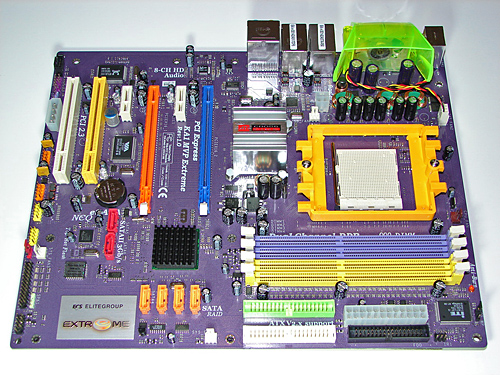
ECS designed a uniquely laid out board with all major connections easily reached except for the Silicon Image 3132 SATA ports. The ECS layout provides excellent clearance for cards and components and it was simple to install in a mid-size ATX case. Although the board features a 3-phase voltage regulator power design it provided excellent stability, power regulation, and allowed for an impressive level of overclocking. The board provides 3 chassis, 1 CPU, and 1 VRM fan header but the bios does not allow temperature based fan control. The overall color combination can be somewhat distracting and when you add in the four flashing blue led lights, you have a recipe for reviving the early Disco years if not having the Fashion Police arrive at your doorstep.
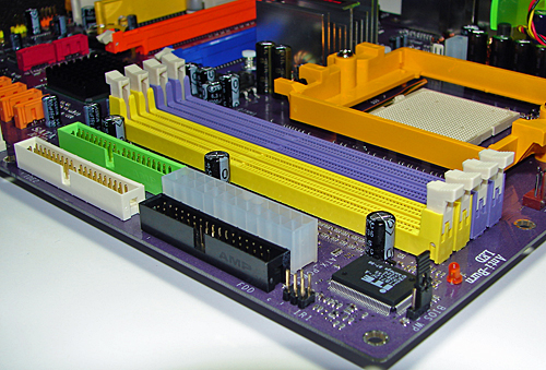
The DIMM module slots' are color coordinated correctly for dual channel setup. The memory modules are easy to install with a full size video card placed in the first PCI Express x16 slot. The black floppy drive and white IDE secondary connectors are conveniently placed along the edge of the board. The 24-pin ATX power connector and green primary IDE connector are located in between the yellow memory module slots and the floppy and secondary IDE connectors respectively.
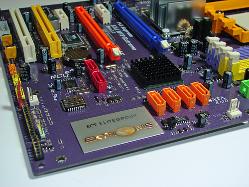
The ATI SATA port connectors are color coded orange while being located beneath the ATI SB450 Southbridge and above the number three chassis fan header. The SATA port connectors did not present any connection issues when utilizing the board in CrossFire operation. The SB450 chipset is passively cooled with a low rise heatsink and located in a position that does not interfere with the PCI Express x16 slots when occupied.
The red Silicon Image SATA ports are inconveniently located below the battery and to the right of the SiL3132 chipset and ECS bios chip. A dual slot video card will render these ports useless when installed in the primary PCI Express x16 slot. The rather large ECS Extreme plaque is located exactly where the Silicon Image SATA ports should reside.
The chassis panel, LPT1 port header, number 2 chassis fan header, and yellow USB 3/4 headers are located along the edge of the board. The red CMOS jumper block is a traditional jumper design located below the chassis fan header.
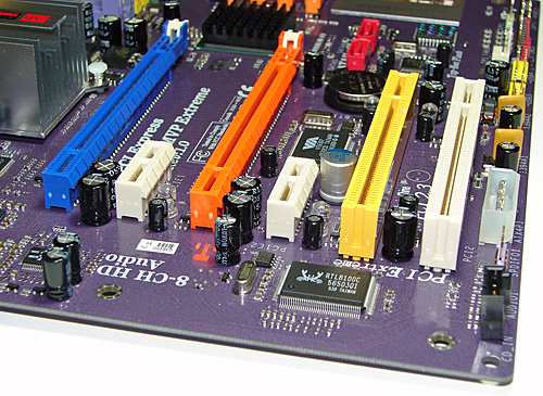
The board comes with (2) physical PCI Express x16 connectors, (2) PCI Express x1 connectors, and (2) 32-bit PCI 2.3 connectors. The layout of this design offers a very good balance of expansion slots for a mainstream board.
The first physical PCI Express x16 connector is color coded blue and located uncomfortably close to the RD480 Northbridge heatsink. The first PCI Express x1 connector is located next followed by the second PCI Express x16 connector that is color coded orange. The second PCI Express x1 connector is located next and followed by the two PCI 2.3 slots.
We did not have any issues installing our ATI X1900XT video cards in the first and second x16 PCI Express slots. These dual slot configuration cards will physically render the first and second PCI Express x1 slots useless. We were able were to utilize these connectors with video cards containing single slot cooling systems.
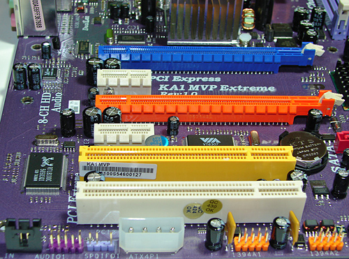
The first PCI Express x16 (blue) connector is considered the secondary slot and the second PCI Express x16 (orange) connector is considered the primary slot. If you utilize one video card it must be installed in the primary slot. ECS ships a shunt card to use in the secondary slot in single video card configurations. When we installed our EVGA 7900GTX or ATI X1900XT CrossFire Edition card in the primary slot it blocked the Silicon Image SATA ports.
The black CD In connector, Front Panel Audio connector, S/PDIF out connector, 4-pin 12V connector, and two orange IEEE 1394A connectors are located along the edge of the board. The 4-pin 12V connector must be utilizing when operating the board with dual graphic cards.
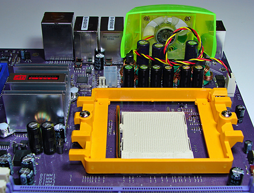
Returning to the CPU socket area, we find a fair amount of room for alternative cooling solutions. We utilized the stock AMD heat sink but also verified several aftermarket cooling systems such as the Thermaltake Big Typhoon and Zalman CNPS9500 would fit in this area during our tests. Due to the high rise heatsink covering the ATI Crossfire Xpress 200 chipset the installation of larger air or water-cooling solutions could be an issue.
The ATI Crossfire Xpress 200 chipset is passively cooled with a large heatsink unit that did not interfere with any installed peripherals. This unit kept the Northbridge cool during overclock testing.
ECS places the ATX12V auxiliary power connector at the top left of the CPU socket area. This connector is located in an unusual position and could hamper airflow with cabling that crosses directly over the CPU heatsink/fan although we did not have any issues in our case. The number one chassis fan header is located below the ATX12V power connector and is difficult to reach once the CPU heatsink is installed.
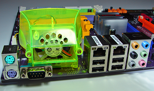
The rear panel contains the standard PS/2 mouse and keyboard ports, serial port, and 4 USB ports. Located to the right of the keyboard and mouse ports and above the serial port is the VRM cooling unit. Although this unit is designed to cool the VRM area we found the performance of the board to be no different with it running or not. Considering the Northbridge and Southbridge are passively cooled, it would have made more sense for ECS to cool the VRM units with heatsinks. The sound of the fan is noticeable at times and the area could have been better utilized for LPT1, 1394A, and/or S/PDIF ports. Located next to the Big Green Unit are the four USB 2.0 ports with the RJ-45 LAN ports on top. The audio panel is located next and consists of 6 color-coded ports that can be configured for 2, 4, 5.1, and 7.1 channel audio connections.
ECS designed a uniquely laid out board with all major connections easily reached except for the Silicon Image 3132 SATA ports. The ECS layout provides excellent clearance for cards and components and it was simple to install in a mid-size ATX case. Although the board features a 3-phase voltage regulator power design it provided excellent stability, power regulation, and allowed for an impressive level of overclocking. The board provides 3 chassis, 1 CPU, and 1 VRM fan header but the bios does not allow temperature based fan control. The overall color combination can be somewhat distracting and when you add in the four flashing blue led lights, you have a recipe for reviving the early Disco years if not having the Fashion Police arrive at your doorstep.
The DIMM module slots' are color coordinated correctly for dual channel setup. The memory modules are easy to install with a full size video card placed in the first PCI Express x16 slot. The black floppy drive and white IDE secondary connectors are conveniently placed along the edge of the board. The 24-pin ATX power connector and green primary IDE connector are located in between the yellow memory module slots and the floppy and secondary IDE connectors respectively.
The ATI SATA port connectors are color coded orange while being located beneath the ATI SB450 Southbridge and above the number three chassis fan header. The SATA port connectors did not present any connection issues when utilizing the board in CrossFire operation. The SB450 chipset is passively cooled with a low rise heatsink and located in a position that does not interfere with the PCI Express x16 slots when occupied.
The red Silicon Image SATA ports are inconveniently located below the battery and to the right of the SiL3132 chipset and ECS bios chip. A dual slot video card will render these ports useless when installed in the primary PCI Express x16 slot. The rather large ECS Extreme plaque is located exactly where the Silicon Image SATA ports should reside.
The chassis panel, LPT1 port header, number 2 chassis fan header, and yellow USB 3/4 headers are located along the edge of the board. The red CMOS jumper block is a traditional jumper design located below the chassis fan header.
The board comes with (2) physical PCI Express x16 connectors, (2) PCI Express x1 connectors, and (2) 32-bit PCI 2.3 connectors. The layout of this design offers a very good balance of expansion slots for a mainstream board.
The first physical PCI Express x16 connector is color coded blue and located uncomfortably close to the RD480 Northbridge heatsink. The first PCI Express x1 connector is located next followed by the second PCI Express x16 connector that is color coded orange. The second PCI Express x1 connector is located next and followed by the two PCI 2.3 slots.
We did not have any issues installing our ATI X1900XT video cards in the first and second x16 PCI Express slots. These dual slot configuration cards will physically render the first and second PCI Express x1 slots useless. We were able were to utilize these connectors with video cards containing single slot cooling systems.
The first PCI Express x16 (blue) connector is considered the secondary slot and the second PCI Express x16 (orange) connector is considered the primary slot. If you utilize one video card it must be installed in the primary slot. ECS ships a shunt card to use in the secondary slot in single video card configurations. When we installed our EVGA 7900GTX or ATI X1900XT CrossFire Edition card in the primary slot it blocked the Silicon Image SATA ports.
The black CD In connector, Front Panel Audio connector, S/PDIF out connector, 4-pin 12V connector, and two orange IEEE 1394A connectors are located along the edge of the board. The 4-pin 12V connector must be utilizing when operating the board with dual graphic cards.
Returning to the CPU socket area, we find a fair amount of room for alternative cooling solutions. We utilized the stock AMD heat sink but also verified several aftermarket cooling systems such as the Thermaltake Big Typhoon and Zalman CNPS9500 would fit in this area during our tests. Due to the high rise heatsink covering the ATI Crossfire Xpress 200 chipset the installation of larger air or water-cooling solutions could be an issue.
The ATI Crossfire Xpress 200 chipset is passively cooled with a large heatsink unit that did not interfere with any installed peripherals. This unit kept the Northbridge cool during overclock testing.
ECS places the ATX12V auxiliary power connector at the top left of the CPU socket area. This connector is located in an unusual position and could hamper airflow with cabling that crosses directly over the CPU heatsink/fan although we did not have any issues in our case. The number one chassis fan header is located below the ATX12V power connector and is difficult to reach once the CPU heatsink is installed.
The rear panel contains the standard PS/2 mouse and keyboard ports, serial port, and 4 USB ports. Located to the right of the keyboard and mouse ports and above the serial port is the VRM cooling unit. Although this unit is designed to cool the VRM area we found the performance of the board to be no different with it running or not. Considering the Northbridge and Southbridge are passively cooled, it would have made more sense for ECS to cool the VRM units with heatsinks. The sound of the fan is noticeable at times and the area could have been better utilized for LPT1, 1394A, and/or S/PDIF ports. Located next to the Big Green Unit are the four USB 2.0 ports with the RJ-45 LAN ports on top. The audio panel is located next and consists of 6 color-coded ports that can be configured for 2, 4, 5.1, and 7.1 channel audio connections.


23 Comments
View All Comments
Wesley Fink - Tuesday, April 4, 2006 - link
A video shunt card is the PCB card used in some Crossfire designs for the second x8 slot when you want the other video slot to be x16. When the card is out you have 2 x8 slots, when it's in you have one x16. nVidia uses a similar "paddle" card on their nForce4 SLI design.ATI also has a BIOS switching option on more expensive Crossfire boards. It turned out the simple paddle was the most trouble-free on the Rx480 Crossfire, but most RD580 use the BIOS-switching design and have been trouble-free.
Beenthere - Tuesday, April 4, 2006 - link
SOS, DD.STILL not ready for Prime time but an "E" for effort with an updated BIOS.
Skip the ATI chipset S939 mobos - they are all flops. Hopefully the socket AM2 mobos will be far better than the S939 ATI based crap. ATI must be really disappointed in the Asian mobo makers who refused to deliver a properly operating mobo.
rjm55 - Tuesday, April 4, 2006 - link
Ever since I read about nVidia paying people to post anti-ATI stuff on Forums I've wondered. Do you suppose it's in NV's interest to drum up that the ATI chipset is immature? I only ask cause the same two names always post crap comments about ATI and the A8R-MVP every time a motherboard review goes up at AT.I also bought an A8R-MVP. I was disappointed it required 2T Command Rate above about 260 until I realized the 2T on Asus was just as fast as iT on other boards. At 2T i reached 320. I haven't had a problem other than that and it's the best $95 I ever spent on a board. I liked it so much I bought an A8R32-MVP which I like ever better.
Why don't you jerks that trash these ATI boards tell us SPECIFICALLY what is wrong and provide some evidence so others can take a look at your problems and fix them for you?