NVIDIA nForce4 Ultra: Biostar's Performance Surprise
by Gary Key on February 16, 2006 12:05 AM EST- Posted in
- Motherboards
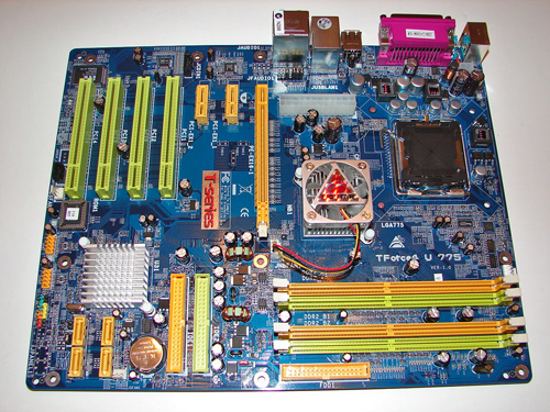
Biostar Tforce4 U 775: Features
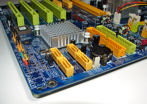
The NVIDIA nForce4 SATA ports are conveniently located below the MCP chipset and to the left of the IDE connectors. The SATA ports feature the new clamp and latch design. Unlike other recently reviewed boards, the SATA ports are not color-coded for primary and secondary operation. We found the positioning of the SATA ports to be excellent when utilizing the PCI slots or IDE port connectors.
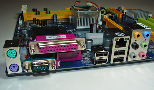
The NVIDIA nForce4 USB connectors, S/PDIF out connector, and chassis panel are located to the left of the MCP chipset along the edge of the board. The BIOS chip is located below the fourth PCI slot. The clear CMOS jumper block is a traditional jumper design located below the number one SATA port connector. The location of this jumper required the removal of the SATA drive cable during repeated usage.
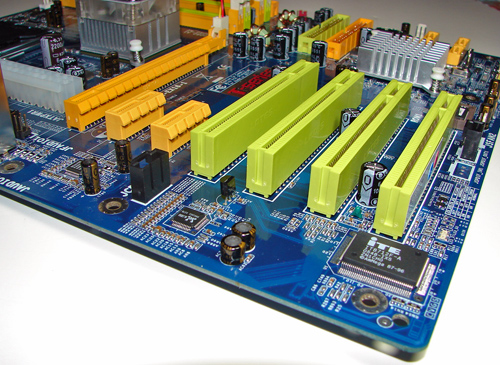
The physical x16 connector is located next to the 24-pin ATX power connector. The (2) PCI Express x1 connectors are located next, followed by the (4) PCI slots.
We did not have any issues installing our EVGA 7800GTX 512MB or ATI X1900XTX video cards in the x16 PCI Express slot. This configuration will physically render the first PCI Express x1 slot useless. We did not have any issues utilizing this slot with video cards containing single slot cooling systems.
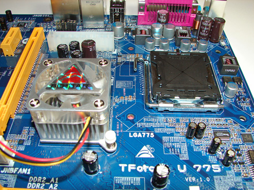
The NVIDIA nForce4 SPP chipset is actively cooled with a large heat sink/fan unit that did not interfere with any installed peripherals. In fact, this unit kept the normally hot SPP chipset cool enough that additional chipset voltage was not a factor in our overclocking tests. Our only concern is the lifespan of the fan as it typically runs at 5500rpm and does generate a slight whirling sound during operation.
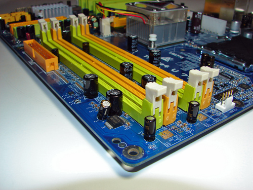
Biostar places the four-pin 12v auxiliary power connector at the top of the CPU socket area, but out of the way of aftermarket cooling solutions. The 24-pin ATX power connector is located above the SPP chipset and next to the x16 PCI Express connector. This 24-pin connector is located in a difficult position and can hamper airflow with cabling that crosses over the SPP heatsink/fan or directly over the CPU heatsink/fan.
The NVIDIA nForce4 SATA ports are conveniently located below the MCP chipset and to the left of the IDE connectors. The SATA ports feature the new clamp and latch design. Unlike other recently reviewed boards, the SATA ports are not color-coded for primary and secondary operation. We found the positioning of the SATA ports to be excellent when utilizing the PCI slots or IDE port connectors.
The NVIDIA nForce4 USB connectors, S/PDIF out connector, and chassis panel are located to the left of the MCP chipset along the edge of the board. The BIOS chip is located below the fourth PCI slot. The clear CMOS jumper block is a traditional jumper design located below the number one SATA port connector. The location of this jumper required the removal of the SATA drive cable during repeated usage.
The physical x16 connector is located next to the 24-pin ATX power connector. The (2) PCI Express x1 connectors are located next, followed by the (4) PCI slots.
We did not have any issues installing our EVGA 7800GTX 512MB or ATI X1900XTX video cards in the x16 PCI Express slot. This configuration will physically render the first PCI Express x1 slot useless. We did not have any issues utilizing this slot with video cards containing single slot cooling systems.
The NVIDIA nForce4 SPP chipset is actively cooled with a large heat sink/fan unit that did not interfere with any installed peripherals. In fact, this unit kept the normally hot SPP chipset cool enough that additional chipset voltage was not a factor in our overclocking tests. Our only concern is the lifespan of the fan as it typically runs at 5500rpm and does generate a slight whirling sound during operation.
Biostar places the four-pin 12v auxiliary power connector at the top of the CPU socket area, but out of the way of aftermarket cooling solutions. The 24-pin ATX power connector is located above the SPP chipset and next to the x16 PCI Express connector. This 24-pin connector is located in a difficult position and can hamper airflow with cabling that crosses over the SPP heatsink/fan or directly over the CPU heatsink/fan.


31 Comments
View All Comments
Calin - Friday, February 17, 2006 - link
What about sorting the graphs based on the min frame rate?:) I guess some people are never happy ;)
Great job, and a nice article!
yacoub - Thursday, February 16, 2006 - link
Once you've owned a passively-cooled motherboard like any of the recent Asus ones, it's hard to even look at one with a fan on it. It also makes shopping for a motherboard a LOT easier because you just cross off all the fan ones right away (unless you're a mod fiend who will actually go through the trouble of buying a chipset cooler or two and rip the fan assembly off the brand new expensive motherboard and hope that cools it well enough).I hope more manufacturers take up the passively-cooled trend.
Gary Key - Sunday, February 19, 2006 - link
I disabled the fan and only witnessed a 2c increase on the MCP. Biostar could have saved a few cents and put towards a Gigabit Lan solution. ;-)Marlin1975 - Thursday, February 16, 2006 - link
Sound and ethernet. Why do companies keep using the realtek junk. bad quality (part and drivers) and juts shows a motherboard company does not care when they use realtek.Any time I see realtek on a board I think the sound and even ethernet were a after thought like "Oh we forgot sound. Lets just put the cheapest POS on there. OK"
COME ON. Good chipset but you come so close then put junk on for sound and so forth.
Myrandex - Thursday, February 16, 2006 - link
For me that issue doesn't matter at all. My Sound Blaster Audigy 2 is still doing its job nicely, and getting a nice onboard sound solution still gets disabled all the same. Now for integrated SB Giga-bite ethernet is something that comes into play with my decisions, and I have been real happy with Giga-byte putting ieee1394b controllers on their boards (and am hoping that external HDD 1394B cases fall in price sooner or later). Integrated wireless is a neat feature some boards have as well.Wesley Fink - Thursday, February 16, 2006 - link
Realtek does have some really cheap audio and LAN chips, but they also have some pretty decent products. In the High Definition area the ALC882 is a really good audio codec with an excellent feature set that produces decent sound and very low noise. If you go through some recent reviews you will see both Gary and I have praised the Realtek ALC882, which is NOT included on this Biostar board :-)Marlin1975 - Thursday, February 16, 2006 - link
yea but you also go on about bad drivers that are STILL in need fo a update and other issues. So sorry but realtek is still junk in my book. That and with so many other options from VIA's envy, c-media, etc... why use something that has problems and are STILL being addressed today?DigitalFreak - Thursday, February 16, 2006 - link
I agree. Using Realtek for LAN is bad enough, but using a PCI solution? That's unacceptible. Even if you don't care about GbE, the CPU utilization is rediculous!Peter - Tuesday, February 21, 2006 - link
The RTL8201 is not a PCI ethernet chip, it's just a PHY companion to the chipset's own engine. This is a research error in the article.http://www.realtek.com.tw/products/products1-2.asp...">http://www.realtek.com.tw/products/products1-2.asp...
The abysmal performance rather more likely stems from transmission errors or poor signal quality - which would point to a damaged or poorly laid out board, or bad cabling.
PHYsical interface chips have zero influence on throughput, as long as signal integrity is being maintained - and as far as that is concerned, Realtek's solution is definitely up to the job. Question is, is the mainboard's layout?
Peter - Tuesday, February 21, 2006 - link
... and of course, we need to keep in mind it's a 10/100 PHY, not a gigabit PHY.