DFI LANParty UT nF3-250Gb: Overclocker's Dream
by Wesley Fink on September 8, 2004 12:05 AM EST- Posted in
- Motherboards
Board Layout: DFI LANParty UT nF3 250Gb
DFI has never been afraid to use stand-out colors on their LANParty boards, and the black and yellow of the LANParty UT will certainly stand out in any side window case.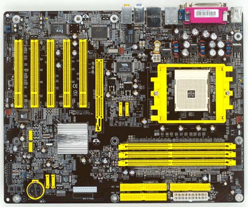
The basic layout of the DFI is excellent, with most everything in the best place in most case designs.
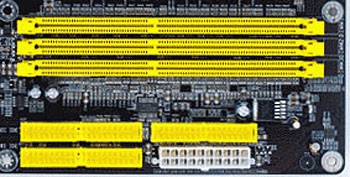
The ATX 20-pin and the 4-pin 12V connector are separated in the DFI, but the locations still work reasonably well. The bulky ATX connector is on our preferred far right edge on the upper half of the board. The 4-pin connector is on the opposite side of the CPU, at the very bottom edge of the CPU socket. The 20-pin ATX is clear of other connectors and should not interfere with air flow. The 4-pin requires a little more care with its near center board location, but the 4-pin is easier to route than the thick ATX cable.
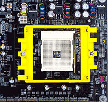
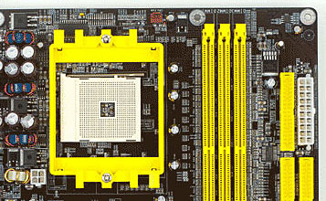
The CPU socket is in the top center of the board. PCI slots are below the socket and memory is to the right of the CPU. There is plenty of room around the Socket 754, so just about any heatsink/fan should work fine. We had no problems mounting a Zalman 7000 on the DFI.
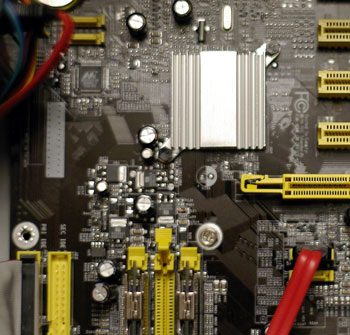
The IDE connectors are in our preferred upper right edge of the motherboard, where they rarely interfere with other connectors. SATA connectors mirror the nF3-250 Reference Board in that 2 are between the AGP slot and the CPU, and 2 are near the lower right edge of the board. The arrangement looks worse than it functions, since the SATA cables are very small. However, SATA connectors are still far too fragile for our liking and anything that gets them away from "high-traffic" areas of the board is preferred. You need to be extremely careful changing a video card or replacing a HSF so that you don't push and break off the SATA connectors between the AGP and CPU. The other 2 SATA connectors are better located near the right edge so that they are out of harm's way.
The floppy connector is ideally located on the upper right edge of the board. It is good to see DFI paying attention to the floppy port location, since many nF3-250 boards put the floppy at the bottom of the board - a difficult location for most full tower cases.
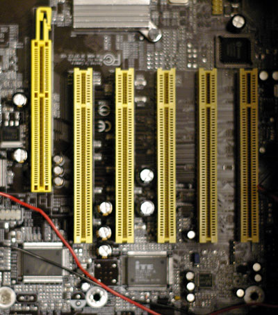
The LANParty UT has 5 PCI slots. The AGP slot uses the common "push to release" lever that works fine with most cards, but can be a real pain with very large top end cards like the nVidia 6800 Ultra. The headers are generally in out-of-the-way locations. However, if you need to use an audio cable with your optical drives, the location at the bottom of the board can be an impossible reach in some tower designs. Like the disappearing floppy, audio cables are rarely required any more, but if you need them, this location can be a challenge in some case designs.
A lot of thought went into the DFI nF3-250Gb board layout. While there are a few things that could be better, overall, the board was easy to install and set up. Most users will be very pleased with the layout.


54 Comments
View All Comments
Bozo Galora - Wednesday, September 8, 2004 - link
#33 - yeah whats up with thatbest perf with one stick, but only 512
and BTW:ZZF had them $135, went out the door fast
ukDave - Wednesday, September 8, 2004 - link
Also, i've just been checking DFI's site and it says it only supports 512MB DIMMs, bit of a bummer cos i was thinking of getting a single 1GB stick, sux0r.ukDave - Wednesday, September 8, 2004 - link
Great article Wesley. Lucky for you guys in the states DFI's RMA process is actually good, here in Europe (UK) we have to deal with DFI NL (Netherlands), and they tbh are crap. So bad in-fact some retailers are debating whether to carry future boards from DFI. I certainly hope they do though, as this board sure looks like a belter, and it WILL be replacing my Asus K8V-SE Deluxe which has no PCI lock (although its still a great board).cnq - Wednesday, September 8, 2004 - link
For everyone looking for "754 overclocking for dummies" guide: it's already been written. Check outhttp://www.dugu9tweaks.net/guides/a64oc/index.html
8NP4iN - Wednesday, September 8, 2004 - link
/me wants oveclocking for dummies guide 2 :]sprockkets - Wednesday, September 8, 2004 - link
No UV reactive green like the other boards? :(JBT - Wednesday, September 8, 2004 - link
Wow looks like a sweet board maybe I can pick up one of these instead of my weak OCing 8KDA3JWesley Fink - Wednesday, September 8, 2004 - link
#23-#26 -You are correct. Since the board was sent without the usual manual, I assumed the SATA ports between the AGP slot and CPU socket were SATA 1 and 2. I now have the manual file, and in fact those ports are identified as SATA 3 and 4.
The 250GB SATA drive was connected to SATA 3 for the overclocking tests.
alex1971 - Wednesday, September 8, 2004 - link
S-ATA 3+4 are OK for HTT > 240 MhzS-ATA 1+2 finished at HTT > 240 Mhz because of the external PHY !!!!
alex1971 - Wednesday, September 8, 2004 - link