Matrox's Comeback Kid - The Parhelia-512
by Anand Lal Shimpi on May 14, 2002 9:00 AM EST- Posted in
- GPUs
Still the king of Image Quality
Matrox has always been held in high-regard for the excellent analog output of their graphics cards. Although many G400 users have since moved on to faster performing graphics cards, most of them miss the crisp display output of their beloved cards. In fact, the only users that don't are those lucky enough to have DVI displays that deal with a digital signal from the GPU where quality is not lost. But for the vast majority of users, analog displays are still an unfortunate reality.
We've explained in previous articles why the analog signal output is generally poor at higher resolutions but Matrox has done some of their own testing to help explain exactly what the limitations of competing graphics cards are.
When the video output signal leaves the RAMDAC it is sent through a series of low-pass filters. As their name implies, a low-pass filter allows low frequency voltages to pass through the filter while preventing higher frequencies from getting through. These filters accomplish two things: 1) they help meet FCC regulations by making sure that only the necessary frequencies get through the VGA output, and 2) they make certain that higher frequency signals do not adversely affect the lower frequency signals that actually matter.
A low-pass filter is generally made up of passive components such as resistors, capacitors and inductors. Because of this a low-pass filter cannot amplify a signal, it can only act as a gatekeeper - allowing certain frequencies to pass and restricting others.
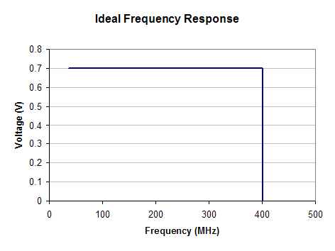
An ideal frequency response curve
The highest frequency that can pass through a low-pass filter is known as the cutoff frequency. Unfortunately a simple low-pass filter isn't perfect; if you set a cutoff frequency at 400MHz you will get frequencies higher than 400MHz passing through. There are two ways of combating this; you can either set the cutoff frequency slightly under the actual frequency you want to cut off at or you can use a higher order filter.
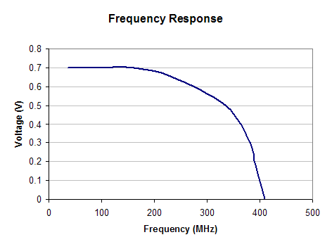
The simplest (and cheapest) is the first approach, setting the cutoff frequency a bit lower than you actually want to cut off at. This results in the following phenomenon in comparison to the ideal frequency response shown above:
The more expensive approach is to use a higher order filter. The order of a filter is directly determined by the components that make up a filter. Without getting into the actual requirements for filters of various orders (it is determined by the (j*w) terms in your transfer function - Vout/Vin) just think of it this way, the more of a certain type of passive component you have in a specific configuration, the higher the order of the circuit.
The benefit of a higher order filter is that the dropoff after hitting the cutoff frequency is much steeper. This means that less of the frequencies you don't want getting through actually make it through the filter. It's a much more elegant approach yet it is more expensive since you have to use more PCB space and more inductors and capacitors.


0 Comments
View All Comments