Gigabyte GA-8TX i850 Socket-423 ATX
by Mike Andrawes on June 3, 2001 12:04 AM EST- Posted in
- Motherboards
The Blue Giant
So far all Pentium 4 motherboards we have seen use a pretty hefty PCB, mainly because of the larger MCH and the extra space needed for the heatsink retention mechanism. The same thing happens here as well, as the bluish PSB measures in at 12 by 9.5 inches.
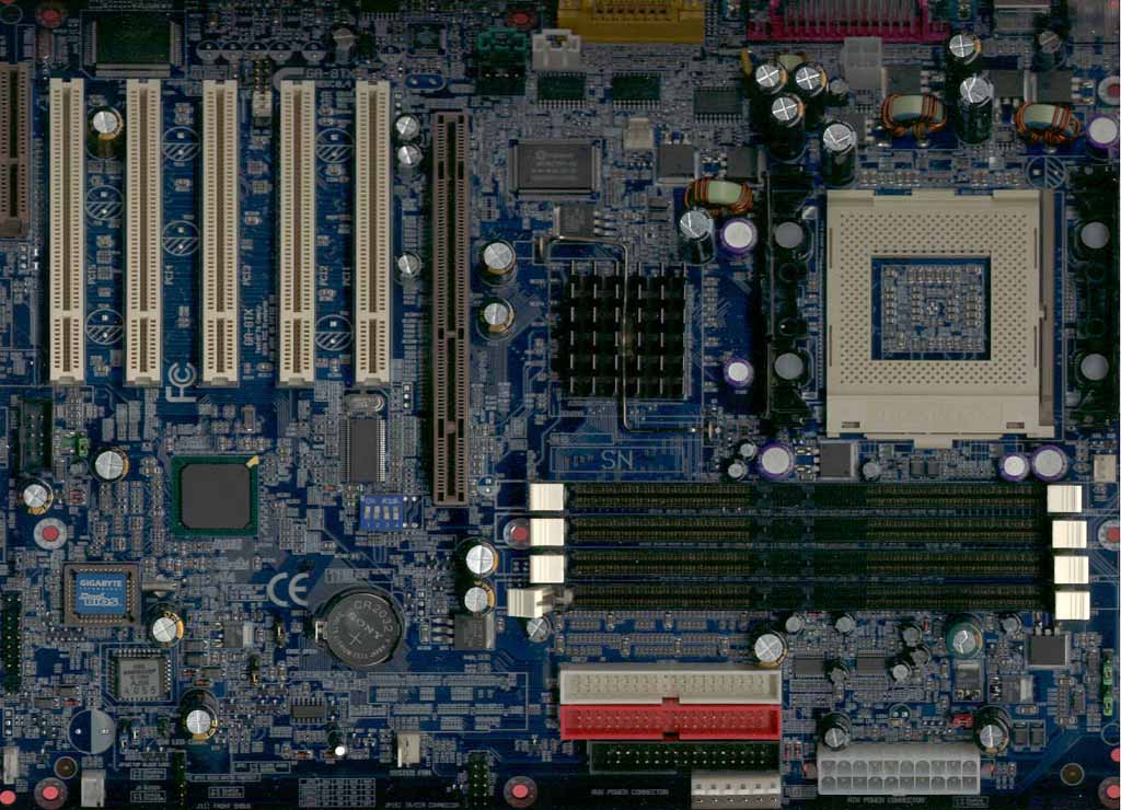
The CPU socket is located quite close to the right edge of the motherboard, but this is actually required if you want to use the new heatsink retention mechanism with a compatible case. Keep in mind that the new Pentium 4 motherboards are using the new ATX 2.03 new specification, so your case should have the necessary mounting holes for the retention mechanism.
With the ASUS P4T, ASUS got around the new specification by including an extra baseboard between the motherboard and the case, so you can stay with your old case to save some money. ASUS also moved the CPU socket’s location, so the baseboard is actually required in all cases, even if you have an ATX 2.03 case. The GA-8TX comes with the heat sink stand mounted to the board through a set of four plastic clips. If you stay with these clips, you could use a non-ATX 2.03 case, but with the Pentium 4 HSF units weighing quite a bit, you do risk the chance of the HSF units falling off while you’re computer is running or during shipping. Indeed, in the manual Gigabyte does suggest that the user change the four clips to the four screws that are also provided with the board.
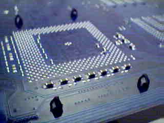
The retention stands are mounted to the boards using plastic clips out of the
box
The four RIMM slots sit in front of the CPU socket and the 82850 MCH. Fortunatley, Gigabyte has left quite a bit of space between the RIMM slots and the AGP Pro slot, so you should have no problem installing or removing memory after the video card has been installed.
The ATX power supply and the AUX power connectors are both located along the front edge of the motherboard, so make sure your case is deep enough so that they are not blocked by drive bays. However, note that the new ATX12V connector is placed at the back of the board, next to the ATX I/O panel and CPU socket.
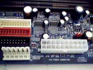
The normal ATX and the
AUX power supply connectors along the front edge

The ATX12V connector
is located at the back of the board
The IDE and floppy connectors are located between the RIMM slots and the AUX power connector, which means that they do not block the use of full length cards in any of the PCI or AGP slots.


0 Comments
View All Comments