Heatsink Guide - AnandTech's new Testing Methodology
by Tillmann Steinbrecher on March 6, 2001 12:00 PM EST- Posted in
- Guides
The Simulator Device
Why use a simulator instead of a real CPU? The simulator solves two problems that are present with CPUs.
First, it is hard to tell how much power a CPU currently produces - the maximum heat emission values specified by the manufacturers are worst-case values, which will not be reached even when running seti@home, prime95, or similar programs. In order to reach the maximum heat emission, CPU manufacturers offer special programs that execute a specific set of instructions to heat the CPU up as much as possible.
In the case of AMD, this program is not available to the public; and according to a heatsink manufacturer, a proprietary PCI card is required to run it. Therefore, we need a simulator device if we want to know how much heat exactly is dissipated by the heatsink.
Secondly, AMD CPUs do not have an internal diode to measure CPU temperature, and in the case of Intel CPUs, the internal diode is not accurate enough for good measurements. So it is not possible to measure the temperature there, where it matters, inside the CPU core. With a simulator, the temperature can be measured right in the simulated die.
This simulator design is not an AnandTech-only project. After the last AnandTech cooler roundup, a small mailinglist was created, where we - Joe Citarella from overclockers.com, Stephen Hoar from burningissues.net, Andrew Lemont from Millenium Thermal, Jim from benchtest.com and John Carcich, discussed various possibilities for testing coolers in a more accurate way.
AnandTech's simulator consits of an aluminum plate milled to the exact shape of an Athlon CPU. On the lower side of the simulator, a foil heater is installed (Minco heater model HK5578R4.6, installed using ArcticSilver epoxy), which provides the heat load. In the center of the simulted "die", a small channel is milled. There, a thermocouple (T-type) is embedded, using ArcticSilver thermal epoxy, too. After installation, the simulated die was lapped.
The CPU simulator is installed in a normal Athlon motherboard (Abit KT7-RAID).
In order to minimize the amount of heat lost through secondary heat paths, the following measures were taken:
- The backside of the heater is covered with a 30x30mm copper sheet, which is glued to the heater and the simulator using ArcticSilver thermal epoxy. This leads the heat emitted on the backside of the heater to the simulator.
- The entire simulator (except for the simulated die, of course) is insulated using self-adhesive Teflon foil (CMC Klebetechnik Order no. 75100, which is temperature resistent to up to 200°C)
- The cavity inside the CPU socket is insulated using Teflon wool
Here are a few pictures of the simulator:
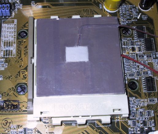
The finalized simulator installed in a motherboard
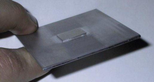
The raw simulator, before sensor and heater were installed
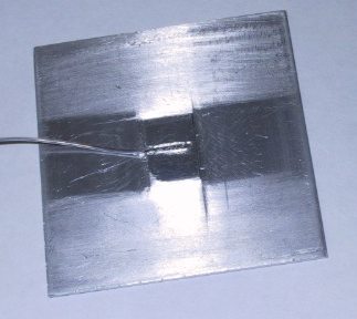
The raw simulator with the sensor, before thermal epoxy was applied
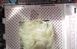
The CPU socket of the test motherboard. Note the groove for the heater's leads,
and the teflon wool inside the socket.
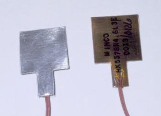
The foil heater used for the simulator (view from front and back)
We chose this heater because, with its size of 19.5x19.5mm, it fits perfectly in the center part of the CPU socket. Its resistance of 4.6 Ohms makes it suitable for simulating common heat loads with a standard 0-25V power supply. Unfortunately, the wattage of this heater is limited; we killed one heater trying to push it to a heat load of 80W. Therefore, in our current setup, we use a heat load of 43W.
The resistance of the heater has a very high tolerance (10%); therefore, a power supply with adjustable voltage is required. Our heater would run at 43W with 14.19V / 3.03A. In future simulator setups, we will be using higher heat loads. For this, a heater with similar mechanical characteristics than the Minco heater, but suitable for higher wattages, would be required. So far we have found none and we would appreciate reader feedback on this point.
For persons with serious interest in how to build their own simulator using our plans - please email tillmann.steinbrecher@anandtech.com and we will send you drawings by email.
A frequently asked question is: Why don't we use the heatsink testing methodology suggested by AMD?
AMD recommends to test heatsinks by drilling a hole into the heatsink, and embedding a thermocouple there. The problem with this method is that it only measures the heatsink performance, but not the performance of the entire cooling system. Not only does the heatsink's performance itself determine the cooling performance under real-world conditions, but the quality of the heatsink contact area (the flatter, the better) and the clip (the more pressure, the better) can have a major effect on cooling performance. For this reason, we chose to use a test setup where the quality of the heat exchange between CPU and cooler is taken into account. This means that if you calculate the cooler C/W based on our test results, you will always get higher values than those obtained using the AMD-recommended method, since our values include the interface.
One thing our simulator setup does not take into account is the cooling of the CPU through the motherboard. In the case of a real CPU, a part of the heat travels through the CPU's pins to the motherboard's leads, where it is dissipated - in other words, the motherboard itself also acts as a heatsink. With our simulator, there is no considerable heat path between the heat source and the motherboard's leads and this effect is not considered. Therefore, coolers which only provide poor air flow to the motherboard (in particular the Alpha models and the Kanie Hedgehog, which suck air away from the cooler) will perform better in our simulator test than in the test with a real CPU.


2 Comments
View All Comments
goonermen - Thursday, November 6, 2008 - link
I wanted to get a hold of the drawings used to build this but I can't seem to get an email through to Tillmann. Can someone help me out??Thanks
Toyotape - Monday, June 21, 2021 - link
Toyotape Corporation designs manufacture and markets industrial tapes and silicone-coated Dupont Kapton® tape, along with an extensive line of pressure-sensitive tapes for use in diverse industrial applications worldwide.