GIGABYTE F2A85XN-WiFi Review: FM2 and Richland in mini-ITX
by Ian Cutress on August 21, 2013 10:00 AM ESTGIGABYTE F2A85XN-WiFi In The Box
Most mini-ITX motherboards on sale today implement the cost-down strategy: the main feature of the package is the motherboard, and extras in that package should be minimal to keep the costs down or push the motherboard into the category below. Unless the motherboard is aimed at a particular market (gamers), mini-ITX owners will not get many platform-specific extras (USB 3.0 brackets etc). The F2A85XN-WiFi is no exception to this, as we get:
Rear IO Shield
Manual
Driver CD
WiFi Driver CD
Two SATA Cables
WiFi Antenna
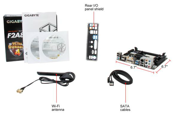
The WiFi antenna is a different design to previous GIGABYTE WiFi models, offering a single adjustable ring platform antenna to increase signal strength and range. Aside from this, there is little to add cost to the SKU.
GIGABYTE F2A85XN-WiFi Overclocking
Experience with GIGABYTE F2A85XN-WiFi
Overclocking a mini-ITX motherboard is often mildly amusing, given the propensity for manufacturers to use a varying standard of power delivery, and/or the space for efficient cooling is perhaps not up to standard. This GIGABYTE motherboard however is set using 40A IR 3550s, the smaller current PowIRStages used from the bigger high-performance brethren. This offered a chance to push the system, even if it was my first overclocking experience with Richland.
In terms of overclocking experience, the automatic overclock options were random at best, with all three causing issues with EasyTune6:
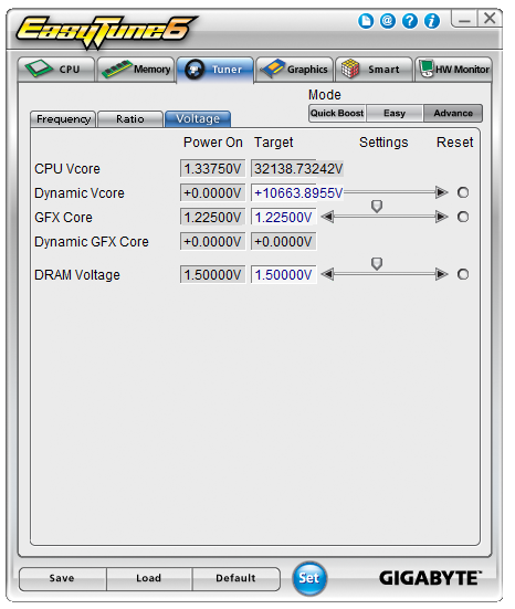
CPU speed also seemed to jump around at stock (no XMP):
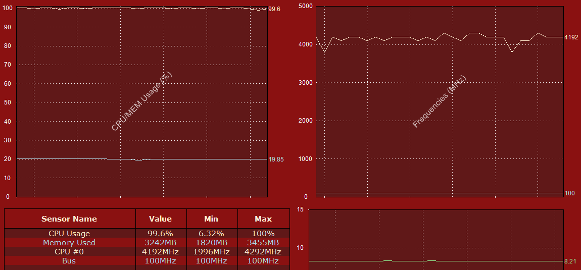
Resulting in perhaps lower results than expected for our stock benchmarks.
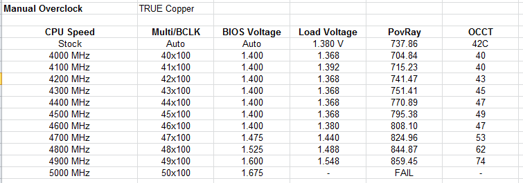
Using the insights gained from automatic overclocking, the manual overclocks performed a lot better. We were able to go through a large amount of overclock at just over stock voltage, before our CPU struggled with 5 GHz, but gave 4.9 GHz stable as a rock.
Methodology:
Our standard overclocking methodology is as follows. We select the automatic overclock options and test for stability with PovRay and OCCT to simulate high-end workloads. These stability tests aim to catch any immediate causes for memory or CPU errors.
For manual overclocks, based on the information gathered from previous testing, starts off at a nominal voltage and CPU multiplier, and the multiplier is increased until the stability tests are failed. The CPU voltage is increased gradually until the stability tests are passed, and the process repeated until the motherboard reduces the multiplier automatically (due to safety protocol) or the CPU temperature reaches a stupidly high level (100ºC+). Our test bed is not in a case, which should push overclocks higher with fresher (cooler) air.
Automatic Overclock:
Using the EasyTune6 overclock options:
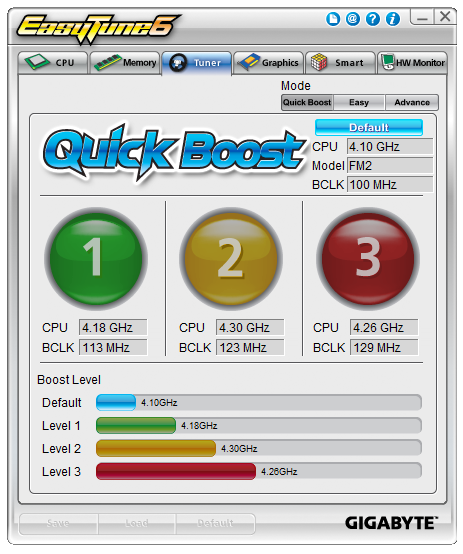
QuickBoost Level 1 was not the 4.18 GHz overclock listed above – we got a 41x106.5 overclock, giving 4366.5 MHz and a load voltage of 1.308 volts. While this gave a PovRay peak score of 759.53, it BSODed quickly while running OCCT.
QuickBoost Level 2 was also a little off, giving a 34x124.82 overclock (4243 MHz). This gave a load voltage of 1.440 volts, a PovRay score of 748.09 and a peak OCCT temperature of 51C.
QuickBoost Level 3 followed a similar tack, giving a 33x131 overclock (4323 MHz). This gave a load voltage of 1.440 volts, a PovRay score of 763.28 and a peak OCCT temperature of 50C.
Manual Overclock:
For our manual overclocks, CPB was disabled in the BIOS and the CPU ratio was manually adjusted. We start at the 40x multiplier and at 1.400 volts, with no changes to LLC. Here are our results:


31 Comments
View All Comments
DanNeely - Wednesday, August 21, 2013 - link
Every time I look at the ultra-crowded layout of an mITX board I'm reminded of how dated the main 24 ATX power plug is and how much it would benefit from being replaced. While they were king in the p1 era with the CPU and PCI busses running on 3.3v directly and most other chips on the board designed for 5V; 3.3 and 5V are barely used at all any more but have 3 and 5 wires in the 24pin cable; while -5V has been removed entirely from modern versions of the spec. Dropping to a single 3.3/5v wire and removing the -5v one would free 7 pins directly; and with only 4 power pins left in the legacy connector (3.3, 5, 2 x 12) there's no need for 8 ground pins either. Probably we could drop 5 of them.This would allow for a successor cable that's only half as large; freeing space on crowded boards and replacing the 24wire cable with a 12 wire one that would be much less of a pain to route in a crowded case. I'm inclined to keep the CPUs 12V separate just to avoid trading one overly fat wire bundle for another and because AIUI the other half of why the CPUs 12V comes in separately is to get it as close to the socket as possible without crowding the area with everything else.
EnzoFX - Wednesday, August 21, 2013 - link
Yes, I've been saying this since ITX was taking hold. It is absurd how held back we are by entrenched standards. It's not in their business to reinvent.Jambe - Thursday, August 22, 2013 - link
I enjoyed this astute observation-comment.Right on.
That is all.
cjs150 - Friday, August 23, 2013 - link
Totally agree on the ATX cable.While we are at why do motherboards virtually never come with the ATX connector being at right angles rather than straight up - we get that for SATA connectors and it seriously improves cable management
flemeister - Friday, August 23, 2013 - link
Not such a good idea for mITX boards, when you might expect to install them in small cases such as the Antec ISK110 or Minibox M350. Right-angled ATX power or sata ports would be blocked off.How about RAM though? Why not use SO-DIMMs that are about 60% the size of regular DIMMs? They're readily available, and are priced the same or very close to the price of regular size RAM. Assuming two sticks of RAM, that would save even more room on the motherboard than a redesign of the 24-pin connector. Just look at the Asus P8H67-I Deluxe for an example. :)
DanNeely - Friday, August 23, 2013 - link
It's not just mITX boards that would have a problem with right angled ATX power sockets. Unless the PSU also included a right angle 24pin cable it would be problematic in any case that uses cable management holes to route the cables behind the mobo tray. Trying to make a 90* bend in that cramped a space would put a lot of torque on the socket; a big ugly loop sticking up allows for a much looser and less stressful bend.DanNeely - Friday, August 23, 2013 - link
For dimm sizes I think it's mostly a capacity issue. For more modest builds it probably doesn't matter; but higher capacities tend to come out a year or two sooner in full size dimms because you can jam more chips onto them if need be. Currently DDR3 dimms and sodimms both max out at 8GB for desktops; but if you're willing to pay the price premium server ram is available in up to 32GB dimms.flemeister - Saturday, August 24, 2013 - link
True, but how about SO-DIMMs on a budget Intel H81/B85 or AMD A55/A75 board? Or one of the low-power Intel Atom or AMD Brazos ITX boards? Or even a budget Z87 ITX board, to avoid the need for a vertically mounted VRM daughterboard (unless that's actually cheaper to do)? More space for surface mounted components, and probably cheaper to make the board? Could also mean less PCB layers?DanNeely - Saturday, August 24, 2013 - link
You're only saving 36 pins/dimm (204 vs 240); so there's no where near enough savings to drop a PCB layer. Beyond that I'd guess that since they do offer some models with SoDIMM slots that they just don't sell as well. If I had to guesses why it'd be that people are more likely to have spare DIMMs laying around than spare SoDIMMs; meaning that the total build cost is lower since the ram is free and/or the cost savings from larger DIMMs are enough to drive shoppers.The one configuration I could see driving some enthusiast/gamer consumption of SoDIMM based mITX boards would be 4 slots instead of only 2 for 32GB max instead of 16; is conspicuous by its absence.
Hyoyeon - Wednesday, August 21, 2013 - link
You mention DisplayPort several times, but this board does not have a DP connector. Where did this come from?