FIC AD11 Socket-A AMD 760 DDR ATX
by Anand Lal Shimpi on February 13, 2001 1:57 AM EST- Posted in
- Motherboards
The Layout
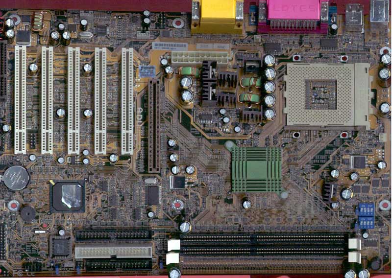
The physical layout of the AD11 hasn't changed much from the engineering sample we received last year. There are a few changes in terms of capacitors and dipswitches but other than that the layout remains the same. The board measures in at about 12" x 8.5" and the first thing we noticed was that the board exhibits a very "busy" design. We mean "busy" in the sense that there are traces and components all over the place. The less PCB you use when designing a motherboard, the cheaper the overall design will end up being and by cramming in as much as possible into such a small footprint FIC is clearly striving to do just that. This layout isn't all peaches and cream, there are a few caveats that are worth mentioning. Get out your red pens, it's time to do some grading.
For starters, and this is a complaint that we have voiced a number of times in other motherboard reviews, the CPU socket is placed too close to the right edge of the motherboard. With the amount of pressure required to mount Socket-A heatsinks, using a flat-head screwdriver to actually get the unit to lock isn’t too uncommon. But with the current position of the CPU socket, getting the screwdriver in between the heatsink clip and your power supply is quite difficult and borderline impossible (without causing damage to your CPU of course). The simple solution to this is to basically remove the power supply whenever installing/uninstalling your CPU or simply do so while the motherboard is out of the case if you are so permitted.
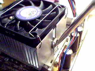
A screwdriver is required to unlock the heatsink. Notice how close the heatsink
is to the edge of the motherboard.
The power supply connector is placed to the left of the CPU socket, close to the audio / game ports. This can also be a problem, as the power cables will have to run over the CPU causing a hindrance to free airflow over your CPU. In order to avoid that problem, you have to make sure the power cables are tied up and carefully tucked out of the way.
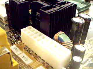
The power supply connector is very close to the tall heatsinks and capacitors.
The final issue we had with the layout was that the two DDR DIMM slots are placed close to the front edge of the motherboard. This forced FIC to relocate the IDE connectors to a position further left on the mainboard. The IDE connectors now block the use of some longer PCI devices, for example the Voodoo5 5000 PCI graphics card. In the end, only a single PCI slot is left completely unobstructed for accommodating full-length PCI cards. Fortunately it is rare that more than one full-length PCI card is used in a system like this, in most cases you won't have any full length cards to worry about.
If this were a server solution, FIC's grade report would have more red X's when it comes to the AD11's layout but since it's not we can simply say that a lot of this is due to the fact that the board is built on a very crowded design. Which would you prefer, a lower overall cost or more space to work with on a motherboard? The decision is yours.


0 Comments
View All Comments