Antec HCP-750 80 Plus Gold
by Martin Kaffei on October 26, 2011 4:35 AM EST- Posted in
- Cases/Cooling/PSUs
- PSUs
- Antec
- 80Plus Gold
- 750W
- High Current Pro
Internal Design and Components
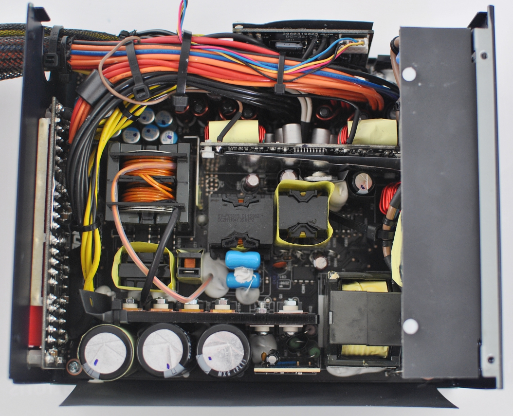
The manufacturer for the HCP-750 is Delta Electronics, just like the HCP-1200, but there are clear differences between the two designs. First, Antec uses a resonant converter like Enermax and Seasonic; on the input side, however, a full bridge circuit is used. Furthermore, the model has two major PCBs, where the smaller board is only used for portions of the EMI filtering. Another significant change is that the power supply is cooled vertically by a large fan. It is striking that no rectifiers are installed in the secondary side—at least no THT components and heatsinks. You'll get the detailed description when we take a look on the secondary circuit in a moment. Where needed, a protective foil against short circuits is used. The output wires are grouped together with serveral cable ties.

Behind the AC input are a total of eight Y-capacitors from China, two common mode chokes, two X-capacitors, a linear choke, a MOV, a thermistor, and a relay. Thus the HCP is well equipped in order to suppress interference from the power grid. Both the phase and the neutral conductor have a large wire cross-section. From this point of view it is noticeable that there is not too much space for ventilation. The small additional PCB on top is the reason for this limitation, but the air is pushed down anyway and flows primarily along the board to the outside. Even though some of the upper ventilation holes are blocked, cooling shouldn't be a problem.
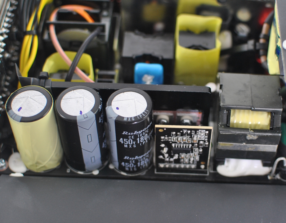
The two rectifier bridges with a common heatsink can rectify an alternating current with an RMS value of 25A—at least with the specified ambient temperature and a corresponding size of the heatsink as in the data sheet. In the power factor preregulator we can find three Rubycon capacitors (MXG, 22mm diameter), two Infineon MOSFETs with a low turn-on resistance, and a PFC choke with its own plastic case The FAN6982-IC regulates the current and is designed for continuous current mode (CCM).
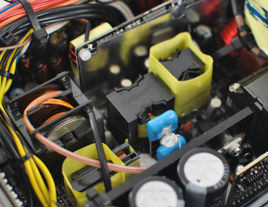
The full bridge circuit consists of two half-bridges (two transistors each), which switch alternately. As usual for this variant, the two half-bridges work with the same duty cycle and are phase-shifted. In this case the phase is not the phase conductor, but the phase angle. Thus there is a phase modulation with two time-shifted oscillations through both half-bridges. Especially for a high power output this circuit topology is ideal.
On the output side the full oscillation is rectified, without the need for using a buffer (chokes). Since the resonant circuit makes zero-voltage switching possible, the switching losses are low and the switching frequency can be increased dramatically compared to hard switching topologies.
The four-quadrant operation is crucial for the transformer size, in which not only the first quadrant can be used, but also all negative values (or positive and negative in Q2 and Q4). This is why the transformer and the remaining passive components in this type of converter can be significantly smaller.
Nobody should be concerned by the small main transformer. Here we have a true 750W power supply, and the design principle of this converter is suitable for 1 KW and more. Important for this design is the separate resonant circuit, so no parasitic effects are used to allow ZVS. This could, for example, be the capacitances between two conductors, transformer windings, or between the gate and bulk terminal of the MOSFETs, plus the natural magnetic fields of all conductors and leakage inductivity.
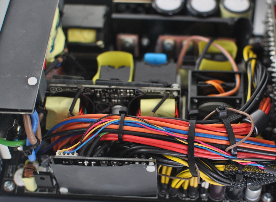
Output side, the two buck converters for +5V and +3.3V are on an additional board. All direct currents run through a circuit made up of rod core inductors and Japanese capacitors. The PCB on the bottom of the 4-pin fan is connected and controlled by the duty cycle. All +12V outputs are protected by OCP, and the cables are fitted with heat-shrink tubing. On the far left we see a small linear regulator for -12V. The MOSFETs for +12V rectification can be found on the back of the main PCB. They are connected via a thermal pad to the housing and can be run almost uncooled at the specified performance. The losses in the semiconductors should be very low.


34 Comments
View All Comments
cjs150 - Wednesday, October 26, 2011 - link
"Antec has patented the use of PWM fans in PC power supplies"And some patent office granted it? Has the world gone mad...patents should only be granted for matters which are innovative and non-obvious. Use of PWM fans in power supplies is completely obvious.
On that basis, I am not buying an Antec power supply. Fortunately there are plenty of other equally good makes
Metaluna - Wednesday, October 26, 2011 - link
*Hopefully* it's a misprint and they just patented some specific PWM control circuit or something, but I'm not optimistic.Oh well, I'm off to patent the idea of replacing the processor in a computer with a faster one.
Rick83 - Wednesday, October 26, 2011 - link
Didn't someone else patent 140mm fans in PSU's, which is why people marketed their 140mm fans as 139mm?Funny nobody patented the fact of putting a fan on a PSU in the first place...
piroroadkill - Wednesday, October 26, 2011 - link
I have a weird feeling it was Zalman, but I'm not 100% on that.slacr - Thursday, October 27, 2011 - link
It's HEC, http://www.hec-group.com.tw/power_supply/ who also owns Cougar.Mumrik - Wednesday, October 26, 2011 - link
"Antec Antec" in the headline and then "Anctec" in the first line....Mumrik - Wednesday, October 26, 2011 - link
"Anctec" is only on the frontpage....Martin Kaffei - Wednesday, October 26, 2011 - link
Fixed! Thanks a lot.marvdmartian - Wednesday, October 26, 2011 - link
before I will trust an Antec PSU in a system again.In 10+ years of building systems, I have had two times where I had a power supply failure, that took out other components at the same time. Believe it or not, it wasn't back in the Powmax days, either.
Both times, Antec PSU's fried, and took out my motherboard with them. Shoot, if I had wanted that kind of performance, I would have kept the Powmax PSU in the case!
Trust is earned, Antec......and you have not done so. Think I'll stick with Corsair, for now.
piroroadkill - Wednesday, October 26, 2011 - link
Some Corsairs are made by Channel Well, the exact OEM that made plenty of Antecs several years back. Though, really, the problem was the Fuhjyyu capacitors. They were absolute garbage and used in a lot of Channel Well designs, including lots of Antecs.When you see the inside of a Channel Well, it's usually obvious, because they use this green crinkly tape around the transformer.
I go to the desired source and buy Seasonic power supplies. Although I do have a Corsair HX520 which is Seasonic built.
I just bought myself a Seasonic X-660. It was costly, but I don't want to fuck about when it comes to power supplies... and it does have a Sanyo Denki fan ;)