A Lesson in User Failure: Investigating the Serial ATA Connector
by Ryan Smith on January 18, 2008 12:00 AM EST- Posted in
- Storage
SATA Anatomy, Failure Anatomy
It’s best to start first with a quick history lesson on the SATA design, as it hasn’t been static through the years. It has gone through some important revisions - some visible and some not – that have shaped the SATA connector in to what we see today. We’d also like to thank Knut Grimsrud, chairman of the SATA International Organization and Intel Fellow in their Technology & Manufacturing group for helping us out with this article and answering some of our questions.
First and foremost, the SATA-IO identified issues early on with the design of the SATA connector, and has revised it several times. This is most obvious in the move from the SATA 1 motherboard connector to the SATA 2 motherboard connector, where the SATA 1 motherboard connector was far more exposed than the SATA 2 connector. This switchover was particularly evident on boards using both native and external SATA controllers, where one would be SATA 2 compliant and the other SATA 1, requiring the different connectors.
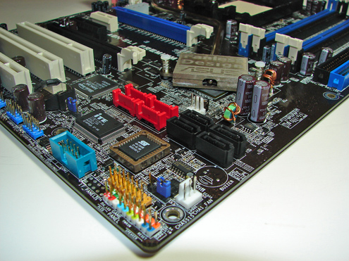
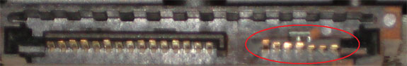
The SATA 2 motherboard connector added shrouding around the connector, which significantly improved the durability of the connector as the shrouding prevented cables from easily bending the wafer part of the connector. Unfortunately this kind of shrouding couldn’t be added to SATA devices, because the standard was designed for use in small devices that don’t have clearance to fit a full shroud. This results in the modern half-shroud design for devices, where the top-half of the connector is shrouded by the device but not the bottom half.
The other significant changes in the standard since its inception have been latching and chamfering. Most SATA devices now have recesses in their top side shroud that allow barbs on SATA cables to latch in to in order to provide downward stability since the underside is the unshrouded side. Chamfering has been added to the square edges of the tongue, and while not a visibly dramatic change, we’ve been told this is one of the primary improvements in strengthening the SATA connector.
Yet in spite of these changes we’ve still managed to do something wrong and break the connector on our hard drive. For the reason why, we’ll start with case designs and cable designs.
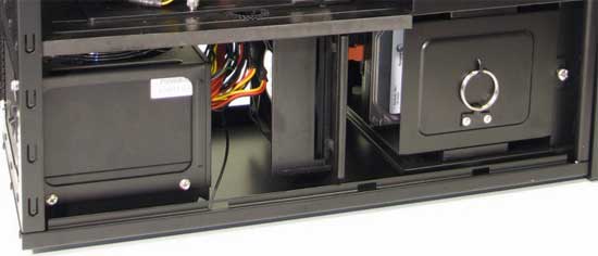
Part of our problem can be attributed to the amount of space we have to work in with the case involved in this investigation, the Antec P182. The P182, like many other cases, doesn’t leave a lot of space behind the primary hard drive bay. For most cases this is because there are motherboard components and cards in the way, while with the P182 it’s a matter of a 120mm fan being located behind the hard drive bay, which helps pull air through the lower chamber. Either way, with this specific case, we measure that we have about 2” between the rear end of a hard drive and the fan, which is very little space to work in.
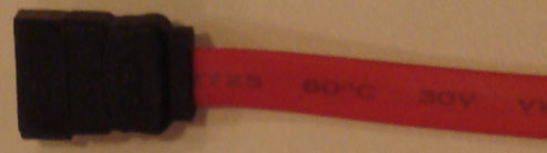
We then come to the cable, in this case it was a bog-standard cable that came with one of the products we’ve used over the years. As we mentioned earlier, SATA cables aren’t quite as flexible as PATA cables when it comes to longitudinal bending, and while we can technically bend a cable completely over at any location, this isn’t great because it causes the cable to pull back in to a more relaxed position. From the tip of the connector, the cable we measured needs about 2.5” of space to bend comfortably.
With the amount of clearance we have being less than the amount of space to need to ideally bend the cable, it becomes obvious that this will quickly become tricky. We need to bend the cable at a sharper angle so that it stays well clear of the fan, which means it’s going to be exerting some force on our hard drive, a generally acceptable but not ideal situation.
And then finally there is the layout of the P182’s hard drive bay. The P182 requires the hard drives to be installed in to the cage at an angle, such that they are on their sides with the bottom pointing towards the bottom of the case, which you can see here. Keep in mind the fact that the top hard drive is on the opposite side of the case from where the motherboard is.
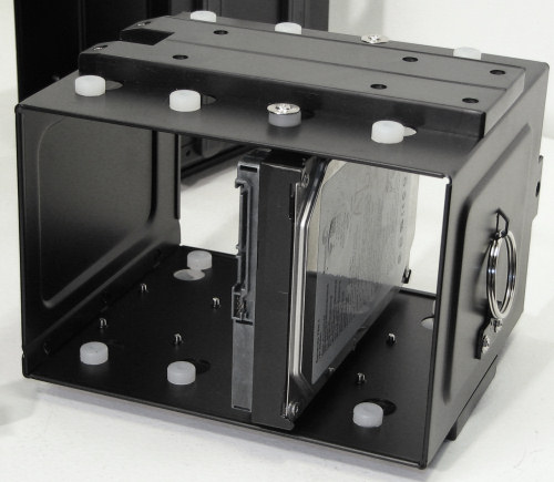
In this combination, we have the anatomy of our failure. Our cable is putting force on the SATA data connector towards the bottom side, which as we covered earlier is the weaker direction to go because it’s not shrouded like the top side is. Furthermore we’re using a SATA-1 style cable without a latch, which means we don’t have said latch to reinforce the connection. It turns out that this is enough force to break the SATA data connector on our hard drive, and when the drive cage was being secured one day the connector broke.


62 Comments
View All Comments
Patanjali - Friday, April 24, 2009 - link
The SATA connector is underengineered for the stress that can be pent up in the cable.This is very annoying when it happens because to try and get the manufacturer to replace it is more trouble than its worth (supply pictures, etc, because they have neer heard of it). At least I can use the drive but have to be very careful every time I slide out its holder (and now every other to not create more) in the Antec Take 4 Rack case.
Other annoying mechanical engineering designs are:
- DBxx connectors = get snagged on any other cable with which they come in contant, and difficult-to-use finger screws with adjacent DB connectors.
- RJxx connectors = ditto, except that the locking lever will break on one of those occasions. Even the shrouded ones are a nuisance because they can be very difficult to remove because of the amount of finely directed finger pressure required to deform the shroud enough to actually push the lever. The best seem to be those with side walls but not a covering shroud - fingers can get to the lever but other cables cannot snag it.
- wide IDE connectors = where there is no pull tab on the cable as pins at one end will get bent as one of the attempts will pull out one end more than the other. Cables will become flakey if manipulated too many times to get them routed around a case.
- most modern compact connectors = resulting from trying to reduce the connector face area on laptops, etc, but forgetting the transmission requirements that dictate a certain minimum cable size and stiffness. Examples are 4pin 1394 and DisplayPort (mini especially).
- consumer audio cables and connections = resulting from trying to reduce the cable weight (opposite of the previous annoyance) so that use will cause the cheap cable or junction to fail before the expensive equipment does.
Patanjali - Friday, April 24, 2009 - link
Basically, most problems result from the mistaken belief of the designers that the connectors will only one be used once at initial installation, forgetting that one of the reasons to have connectors rather than permanent soldering is to be able to change them around as circumstances change.Ionman - Tuesday, March 10, 2009 - link
I've found the SATA connectors to be the flimsiest of any by far... I live in India where dust is a real issue so that might elevate my problems. I have had problems with my RAID 0 array where my computer would refuse to boot even though the controller was detecting both the drives. A quick chkdsk from the windows cd would solve the problem. In the end i realized that it was the SATA connectors/cables that was the problem. Changed both the cables and voila problem solved. I've encountered the same problem one more time. Space is not really much of an issue on my pc and the cables dont have much stress on them, I guess. But its really frustrating to have a problem like this... takes days to figure out what is really going on.Mr Ravageo - Sunday, March 1, 2009 - link
Good article, it makes you think about what you are doing when you stick your hands in hundreds of dollars of computer investment. As always, planning ahead will always save you time and money on anything, not just a computer build. For those linked here by newegg, I just bought a P182 and I love it; a good solid quiet case. While, I understand the choice of using the bottom HD tray for this demonstration (SATA connector failure/choice); the primary HD bay is in the top compartment. Unless you have super long video cards, this is where the main HD should go. In this compartment a straight cable will work fine. It is always a good to have many different types of connectors on hand (PSU extender cables, 90 deg SATA, etc).Happy Building
anti nowhere - Wednesday, January 30, 2008 - link
This is funny. This same thing happened to me about 2 years ago when I installed my very first and very new SATAII HD. I got out a flashlight and my pliers....lined up the pins and just pushing the cable with broken interface still on it, back into the HD. Then I glued that b*tch right back on there. Has worked ever since and with no problems. Next time I will throw the piece of crap away and buy a new one.Zepper - Tuesday, January 29, 2008 - link
Yes we can find fault with the SATA mechanical design spec - the one for desktop drives is totally inadequate for the environment since it is the same as for notebook drives where the drive is installed once and generally stays there 'til it dies. Using notebook connectors in a desktop environment is absurd!. The power and data connection should be totally surrounded by plastic on the desktop drives like the mobo and drive connectors for PATA cables. That would up the strength by at least an order of magnitude - nothing stopping you from super gluing a slab of plastic along underneath your drive's connectors. The cables will still fit and and you'll have added breakage protection. And for those who haven't broken their connectors yet, here is a cable set that will add a bit of strength for you non-WD drive owners:
http://www.newegg.com/Product/Product.aspx?Item=N8...">http://www.newegg.com/Product/Product.aspx?Item=N8... too bad they didn't add the metal "SATA 2" latches - I guess it was just easier to use the notebook female connector (comes in many colors but I've only seen them under this brand name). Use this plus gluing on a bottom rail for double protection. WD offers a similar cable for their SATA drives only.
. Another option is to get a "Kublai Kage" (c) 2007 by me for your case - it comes with four, plastic, slide-in trays for the drives. It comes with the Silverstone Kublai cases (see my review of the KL01 here: http://www.techimo.com/articles/">http://www.techimo.com/articles/ -for pix) and will soon be available separately as the SST-CFP52 and you can get up to four of the SATA hot-swap brackets (SST-CP05) for the cage (the Kublai cases come with only one of them. One place has the CP05s now for $8.00 each, though list is supposed to be $5.00. Since you won't be manually plugging/unplugging and the connections are fairly well concealed, damage should be unlikely. $40.00 total for the Kage and 4 brackets makes this the least expensive SATA hot-swap solution available and will fit most any case with 3 free 5" bays. .bh.
jdizzle1337 - Thursday, January 24, 2008 - link
Ryan i LOLed when i read your article, because the exact same thing has happened to me with that exact same case (well P180B, but w/e ;P). Really ticked me off because it ruined my brand new Seagate 500GB Barracuda, and that was back when they were new and $200, not the $100 that they are now.After looking back at my situation i was dumb and threw the black sliver of plastic that fell off away, after realizing this is integral to securing and completing the SATA connection i attempted to superglue the cable to the SATA pins on the drive.....this causes the board to have a short circuit and thus it will not turn on. I have resigned myself to the fact that the perfectly new unused drive is junk. I have thought about seeing if i can RMA though Seagates cross ship warranty process, but i think they only cover internal failures as opposed to physical damage.
Anyway my methodology for drive installation in the P18x is:
A) Screw the drives into the drive cage
B) Connect the SATA connectors to the drives
C) Hold the cage over the slot that it goes into and let the SATA cables drop down into the drive bay area
D) Slowly lower the drive cage into the drive bay while threading the SATA cables through the cord exit that leads into the main case area that holds the motherboard.
E) Connect the SATA cables to the motherboard.
You have to work gingerly, its all about lowering the drive cage into the bay slowly, and making sure a power connector doesn't get caught on tension and push into one of the data connectors. If you force it down or let it drop in on its own weight the drives farthest to the bottom will likely snap the back of their SATA connectors and the upper ones will have strained plastic around the connector. Just hold the drive cage by the little keyring looking thing and slowly lower it and you will be good ;P
smut - Wednesday, January 23, 2008 - link
and I sent into WD and they fixed it! I have since bought the latch on connectors and use the angled ones if need be. I continue to buy WD drives these days because of the customer support given. They RMA'd the drive and sent it back, good as new. If anyone has a WD drive you may be able to get it fixed, its worth a shot. The worst they can say is no.Symmetriad - Tuesday, January 22, 2008 - link
Can you do a writeup on the ridiculous disconnect between motherboard and case manufacturers on power switch/front panel connectors next? The hideous lack of standardization has consistently been one of the biggest hassles of building a new PC for years.smut - Wednesday, January 23, 2008 - link
I agree wholeheartedly with your comment! Its very annoying!