Intel D975XBX: Intel brings their Bad-Axe to Market
by Gary Key on January 26, 2006 12:05 AM EST- Posted in
- Motherboards
INTEL D975XBX: Features
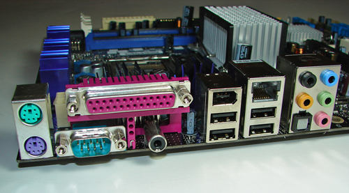
The Intel SATA ports are conveniently located below the ICH7R chipset and to the left of the primary IDE connector. The SATA ports feature the new clamp and latch design. Unlike other 975x boards, the SATA ports are not color-coded for primary and secondary operation. We found the positioning of the SATA ports to be excellent when utilizing the ATI CrossFire cards in the primary and secondary PCI Express connectors.
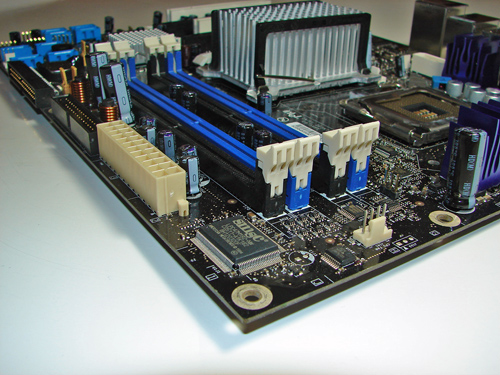
The Silicon Image SiI 3114 SATA RAID port connectors are clustered on the left edge of the board. The Intel USB connectors and chassis panel are located below the SiI 3114 port connectors and to the left of the Intel SATA port connectors. The BIOS configuration jumper block is a traditional jumper design located above the IDE port connector. The location of this jumper was acceptable during repeated usage.
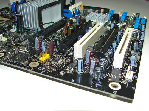
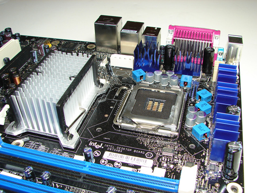
The first physical x16 connector located next to the MCH heat sink is the primary PCI Express connector and is set up for electrical routing in x16 or x8 operation. The x16 interface supports full duplex transfers up to 8 GBytes/second in x16 operation and single-ended transfers are supported up to 4 GBytes/second in x8 operation.
The next physical x16 connector is the secondary PCI Express connector and is set up for electrical routing in x8 operation. This connector also fully supports x4 and x1 PCI Express add-in cards. The final physical x16 connector is set up for electrical routing in x4 operation and fully supports x4 or x1 PCI Express add-in cards.
We did not have any issues installing an ATI X850 Crossfire Edition setup in the primary and secondary x16 PCI Express slots. This configuration will physically render the first PCI slot useless. There were no issues utilizing this slot with video cards containing single slot cooling systems.
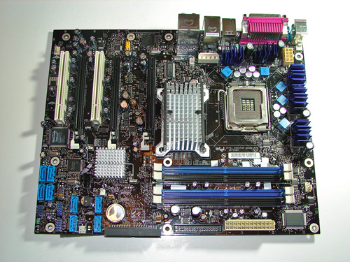
The MCH and ICH chipsets are passively cooled with heat sinks that do not interfere with any installed peripherals. In fact, this system kept the chipsets cool enough that additional chipset voltage was not a factor in our overclocking tests. Intel places the eight-pin 12V auxiliary power connector at the top of the CPU socket area, but out of the way of most aftermarket cooling solutions. However, the 4-pin auxiliary power connector is located in a difficult position and can hamper airflow with cabling that crosses over the heat sink.
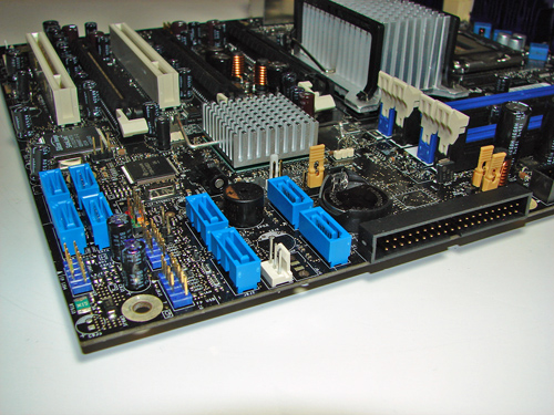
The Intel SATA ports are conveniently located below the ICH7R chipset and to the left of the primary IDE connector. The SATA ports feature the new clamp and latch design. Unlike other 975x boards, the SATA ports are not color-coded for primary and secondary operation. We found the positioning of the SATA ports to be excellent when utilizing the ATI CrossFire cards in the primary and secondary PCI Express connectors.
The Silicon Image SiI 3114 SATA RAID port connectors are clustered on the left edge of the board. The Intel USB connectors and chassis panel are located below the SiI 3114 port connectors and to the left of the Intel SATA port connectors. The BIOS configuration jumper block is a traditional jumper design located above the IDE port connector. The location of this jumper was acceptable during repeated usage.
The first physical x16 connector located next to the MCH heat sink is the primary PCI Express connector and is set up for electrical routing in x16 or x8 operation. The x16 interface supports full duplex transfers up to 8 GBytes/second in x16 operation and single-ended transfers are supported up to 4 GBytes/second in x8 operation.
The next physical x16 connector is the secondary PCI Express connector and is set up for electrical routing in x8 operation. This connector also fully supports x4 and x1 PCI Express add-in cards. The final physical x16 connector is set up for electrical routing in x4 operation and fully supports x4 or x1 PCI Express add-in cards.
We did not have any issues installing an ATI X850 Crossfire Edition setup in the primary and secondary x16 PCI Express slots. This configuration will physically render the first PCI slot useless. There were no issues utilizing this slot with video cards containing single slot cooling systems.
The MCH and ICH chipsets are passively cooled with heat sinks that do not interfere with any installed peripherals. In fact, this system kept the chipsets cool enough that additional chipset voltage was not a factor in our overclocking tests. Intel places the eight-pin 12V auxiliary power connector at the top of the CPU socket area, but out of the way of most aftermarket cooling solutions. However, the 4-pin auxiliary power connector is located in a difficult position and can hamper airflow with cabling that crosses over the heat sink.


34 Comments
View All Comments
BigP - Wednesday, June 21, 2006 - link
Im a self build Virgin - but I'm going in at the deep end. Intel's site makes their Dual Core stuff sound awsome!(a) Is it?(b)Should I look to spend my cash elsewhere when considering a motherboard/processor?Gary Key - Saturday, July 15, 2006 - link
This board is fine for stock performance and if you get rev-0304 it works very well with Core 2 Duo.FOXY25 - Sunday, February 4, 2007 - link
hi that are my system setting. My system sometimes make complete restart and i dont know why. I have change entire board with another and nothing. Do y think that could be in memory i have 2x DDR2 1024 MB at 800 Mhz Kingmax. thanks for answer.Foxy====== Board ======
Manufacturer Intel Corporation
Product Name D975XBX
Version AAD27094-306
Serial Number BQBX645001ND
BIOS Version BX97510J.86A.1476.2007.0119.1334
BIOS ROM Size 512 KB
BIOS Release Date 19.1.2007
====== Processor ======
Manufacturer Intel(R) Corporation
Processor Name Intel(R) Core(TM)2 CPU 6400 @ 2,13GHz (2 Cores)
Bus Speed 1067 MHz
Processor Speed 2,133 GHz
Stepping 6
Form Factor Other
Hyper-Threading Technology Status Not Supported
====== Cache ======
L1 Cache Data Cache 32 KB, Code Cache 32 KB Per Processor Core
L2 Cache 2048 KB Unified Cache (2048 KB Cache Per 2 Cores)
====== Memory ======
Error Correction Single-bit ECC
Maximum System Memory 4 GB
Memory Slots 4
---- CHAN A DIMM 0 ----
Socket Designation CHAN A DIMM 0
Current Memory Type DDR2
Installed Size No Module Installed
---- CHAN A DIMM 1 ----
Socket Designation CHAN A DIMM 1
Current Memory Type DDR2
Installed Size 1024 MB
Memory Speed 800 MHz
---- CHAN B DIMM 0 ----
Socket Designation CHAN B DIMM 0
Current Memory Type DDR2
Installed Size No Module Installed
---- CHAN B DIMM 1 ----
Socket Designation CHAN B DIMM 1
Current Memory Type DDR2
Installed Size 1024 MB
Memory Speed 800 MHz
====== Onboard Devices ======
#Device Type Ethernet
Device Description Intel (R) 82562 Ethernet Device
Device Status Enabled
#Device Type Sound
Device Description Intel(R) Azalia Audio Device
Device Status Disabled
#Device Type Other
Device Description Silicon Image 3114 SATA RAID Controller
Device Status Disabled
#Device Type Other
Device Description Texas Instruments TSB82AA2 1394A/B Controller
Device Status Disabled
====== Hard Drive ======
#Model ST3320620AS
Max. Transfer Mode UDMA 6 (ATA/133)
Active Transfer Mode UDMA 5 (ATA/100)
S.M.A.R.T. Status Enabled
Size 298,09 GB
#Model ST380811AS
Max. Transfer Mode UDMA 6 (ATA/133)
Active Transfer Mode UDMA 5 (ATA/100)
S.M.A.R.T. Status Enabled
Size 74,53 GB
JarrettV - Thursday, February 23, 2006 - link
Does this board support dolby digital live in the sigmatel audio chipset? I'm looking to replace my old SoundStorm setup.Also, does Intel High Definition = Dolby Digital Live support?
neilfeier - Wednesday, February 22, 2006 - link
Unlike most users of this motherboard that want to use the dual x8 PCIe slots for graphics, I want to use them for benchmarking a pair of x4 data acquisition boards we are developing. I want to test max rates to and from memory, as well as peer-to-peer transfers between the two boards (assuming the MCH allows this).So my question is: Do you think I can I put a x16 or x8 PCIe graphics card in the third x4 PCIe slot hanging off the south bridge? I don't care about graphics performance too much, I just want a dual monitor card that will work in that slot and leave the main two slots free.
And ideas on this would be helpful. Thanks!
Gary Key - Wednesday, February 22, 2006 - link
I will try it this weekend and report back.neilfeier - Friday, March 3, 2006 - link
Thanks Gary, I anxiously await the results of your experiment.Neil
Gary Key - Thursday, March 9, 2006 - link
Hi Neil,I had video working in this slot. I updated to the new bios release today and will test the performance in a couple of days.
Thanks,
Gary
Gary Key - Tuesday, March 28, 2006 - link
Neil,Performance is average but it works.
Gary
Missing Ghost - Monday, January 30, 2006 - link
error! That's not how pcie works! pcie is always full duplex, and never single-ended!