The MSI X299 SLI Plus Motherboard Review: $232 with U.2
by Joe Shields on November 29, 2017 8:00 AM EST- Posted in
- Motherboards
- MSI
- X299
- Skylake-X
- Kaby Lake-X
- SLI Plus
Visual Inspection
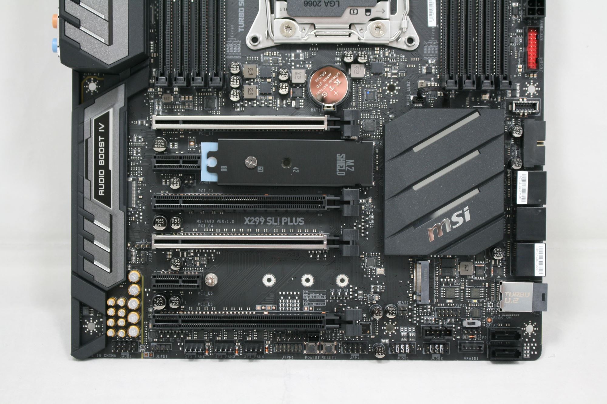
The MSI X299 SLI Plus is an all black motherboard with shrouding covering the back panel IO as well as the audio bits further down the board. At the top of the shroud, we find it has the SLI Plus name, while the bottom advertises the Audio Boost IV feature. The chipset and power delivery heatsinks are attached well and do a good job at managing the heat created in our test environment, even while overclocking.
Onboard lighting through RGB LEDs is tastefully done and found only in the stripes across the power delivery and chipset heatsinks. The chipset LEDs will likely be obscured by a video card, unfortunately. Outside of POST LEDs, there are white LEDs at the top of each DRAM slot which light up when the slots are populated. These LEDs also sync with whatever theme is selected through the software. Something to note for system builders is the RGB LEDs are not able to go to a single color. There will always be a cascade of the color set. For example, if Blue is set, the other colors get lighter. I don't think this looks bad, but for builders who want one color with all LEDs, it won't be this board (or the LEDs will have to be disabled). If integrated lighting isn't enough, the board has two RGB LEDs headers as well.
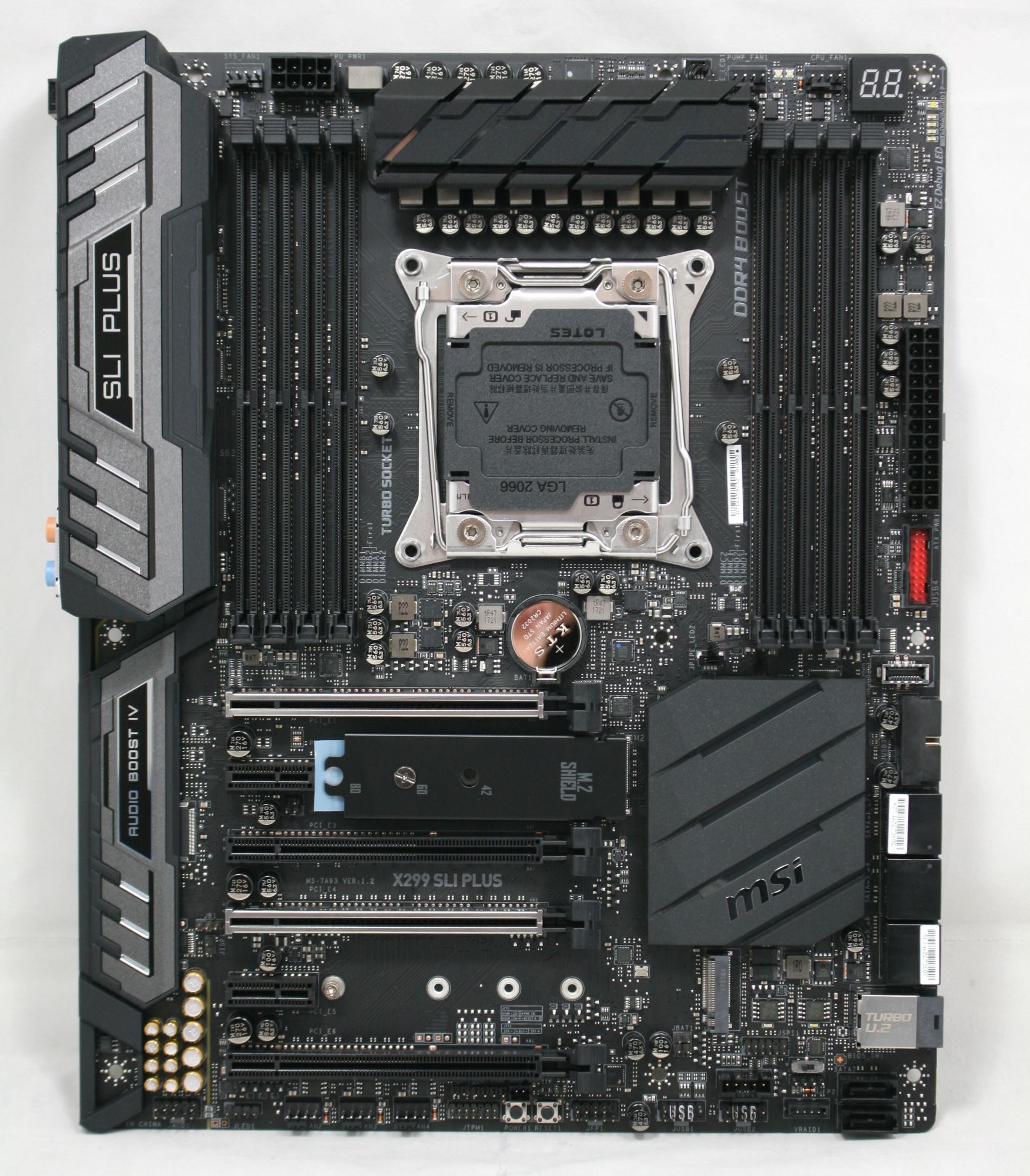
In looking around the board, there are a total of six fan headers. Across the top are is a System fan header (by the 8-pin EPS plug), a pump fan header, and a CPU fan header (above the right set of DRAM slots). The remaining three system fan headers are located at the bottom of the board below the last PCIe slot. The 4-pin pump fan is able to deliver 2A (24W) through the four pins which should be enough for most pumps on the market. All headers auto detect 3-pin and 4-pin devices, and are able to control them accordingly through DC or PWM methods.
The socket area is pretty fairly clean on the top and sides with capacitors lining up across the top of the 10-phase power delivery (more details later), but the bottom of the socket is fairly busy with a couple of capacitors precariously close to the socket. Like the Tomahawk Arctic, nobody typically uses these cheaper boards for extreme overclocking, however, be sure care is taken when mounting the heatsink.
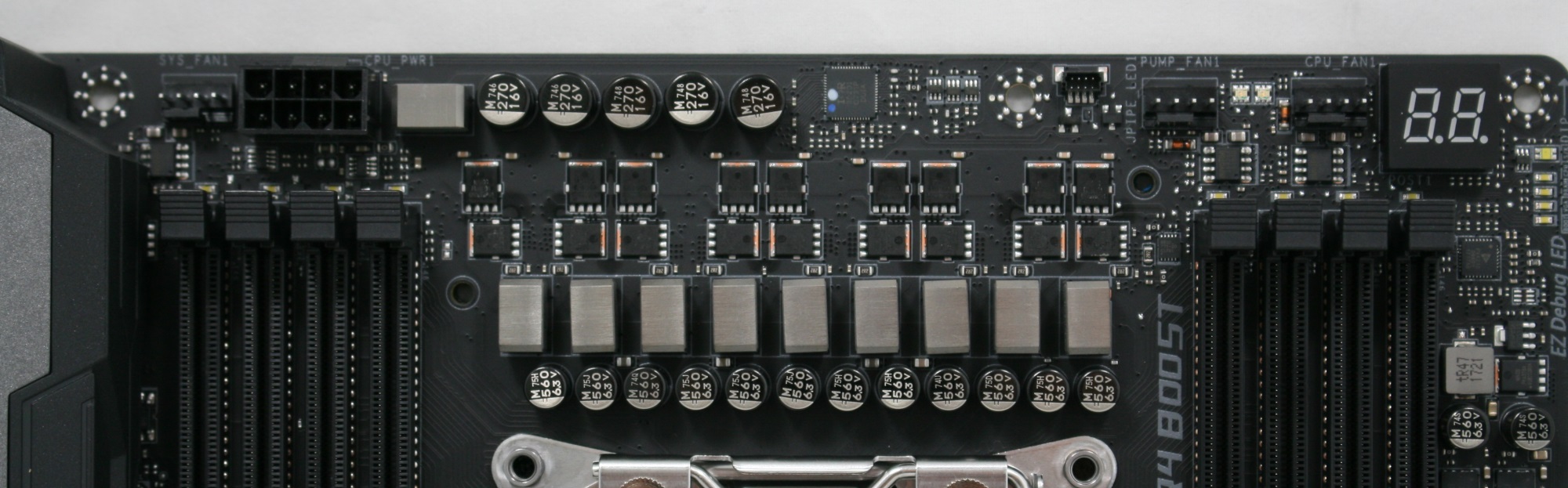
The 10-phase VRM is the same we found on the Tomahawk Arctic, so it is really 4-phase and doubled. At the helm is an International Rectifier IR35201 8-channel controller with Nikos PK616BA and PK516BA MOSFETs. The phase double duties are handled by four Infineon IR 3598 MOSFET drivers. Sending all the power to the VRMs is a single 8-pin EPS 12V connector located on the top of the board above the left set of DRAM slots, although most new X299 boards will have two to spread the load, especially when overclocking. A 24-pin ATX connector powers the rest of the board. LIke the Tomahawk Arctic, the heatsinks did get warm to the touch, but we did not see throttling in our testing.
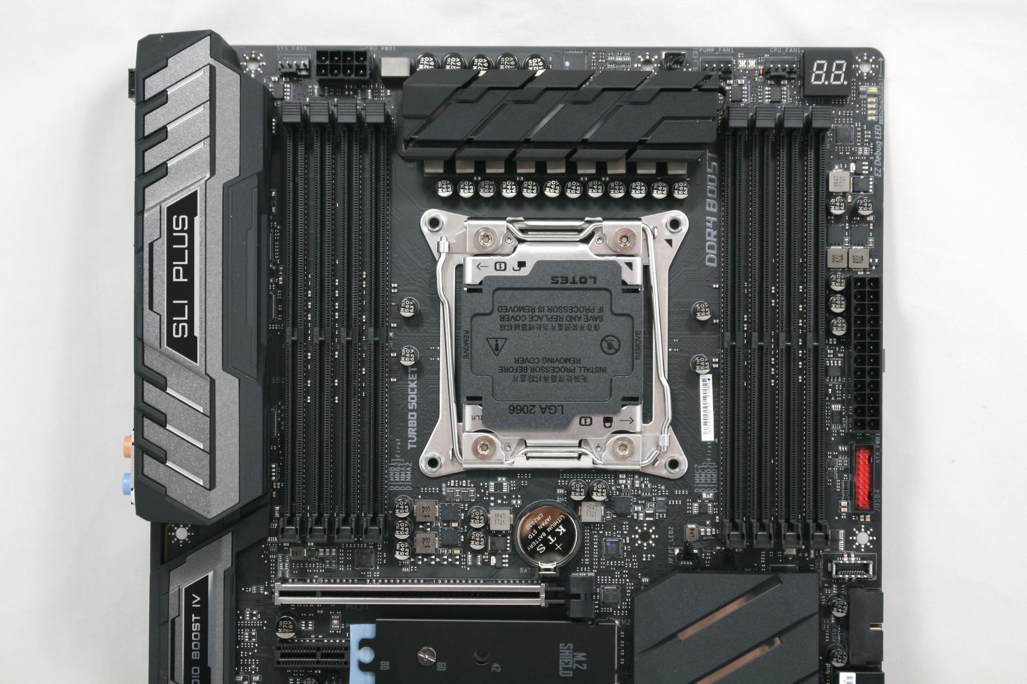
DRAM support on the SLI Plus is up to 128GB with speeds supported to DDR-4133 in quad channel, while in dual channel, supported speeds increase to DDR4-4500. Like the Tomahawk Arctic, there are LEDs above each DRAM slot that when populated are lit up in white. The SLI Plus DRAM slots are not reinforced and use a one latch system to keep the sticks in place.
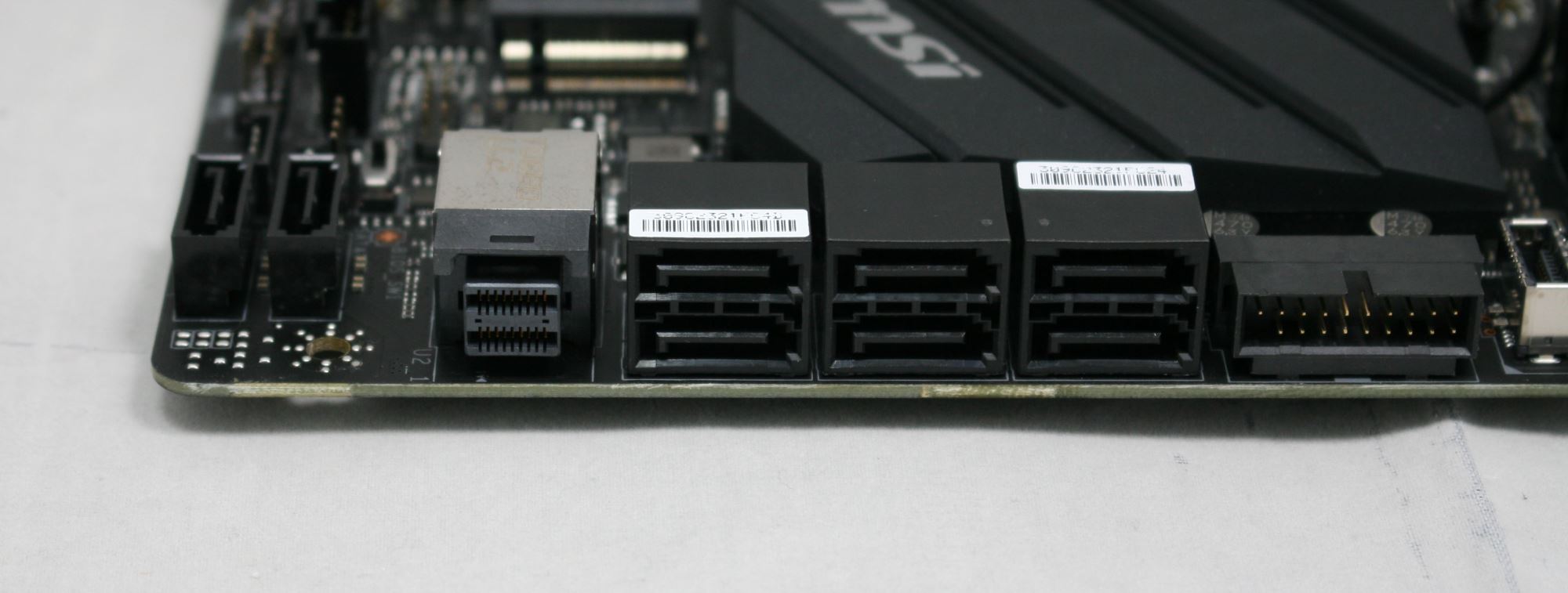
The right-hand side of the board, starting at the top, we get a two-digit debug LED display, as well as four debug LEDs just below it. The four LEDs cover Boot, VGA, DRAM, and CPU. If the VGA is having issues upon POST then that LED will remain lit up. Below the 24-pin ATX power are two front panel USB 3.0 (5 Gbps) headers with one angled vertically, the other laying horizontal. Between them is the USB 3.1 (10 Gbps) Type-C port for the front panel. Down the line are eight SATA ports and a U.2 port.
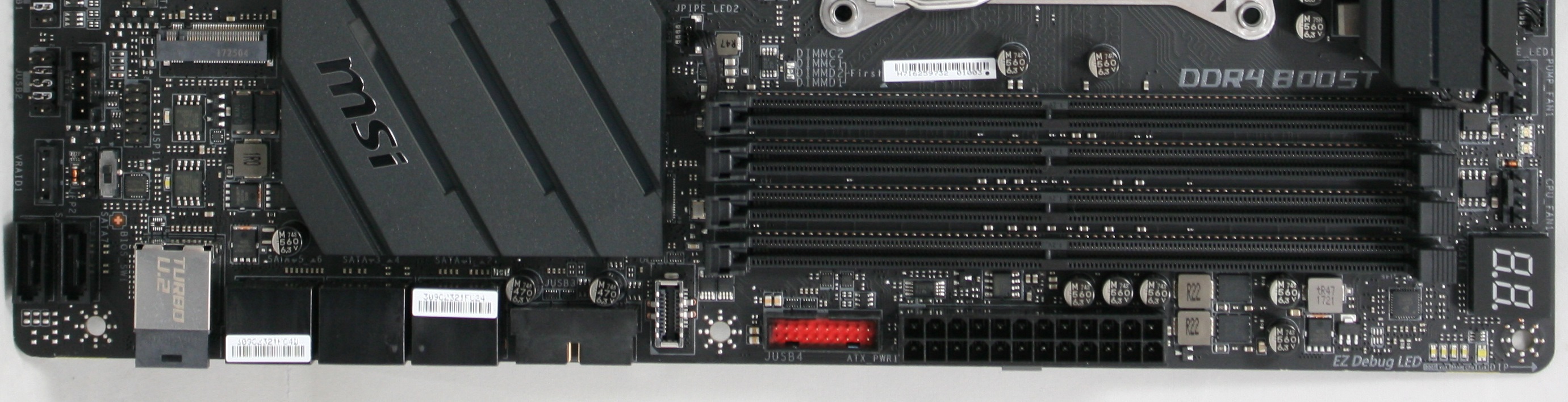
For storage, we get a total of eight SATA ports (native to the chipset) a U.2 port (shares bandwidth with the third PCIe slot), as well as two M.2 slots (shares bandwidth with SATA when in SATA mode). The top M.2 slot does have a heatsink on it to assist in M.2 cooling. This first M.2 slot can fit up to an 80mm module, while the second slot, which does not have a heatsink, supports up to a 110 mm module. The first M.2 slot supports both SATA and PCIe based modules. When using a PCIe based drive in this slot, all SATA ports are available. If the module is SATA based, SATA1 is disabled. The second M.2 slot also supports both SATA and PCIe modules - when used with a SATA based device, SATA5 is disabled. If a PCIe M.2 device is used, SATA5-8 are disabled. See page 37 in the manual for details.
When a device is connected to the U.2 port, the third PCIe slot is disabled. This shouldn't be a big concern for most as that specific PCIe slot is not the preferred location for multi-GPU setups.
Across the bottom, starting from the left-hand side, is the Realtek ALC1220 audio codec hidden beneath the shroud. We can see the Chemicon audio caps as well as physical PCB isolation for minimizing interference. Below the audio bits is the front panel audio connector, while next to it sits an RGB header and three system fan headers. There are small power and reset buttons in the middle along with two USB 2.0 headers to the right. A 5-pin Thunderbolt header is found above those while the VROC connector sits below the dual bios switch.
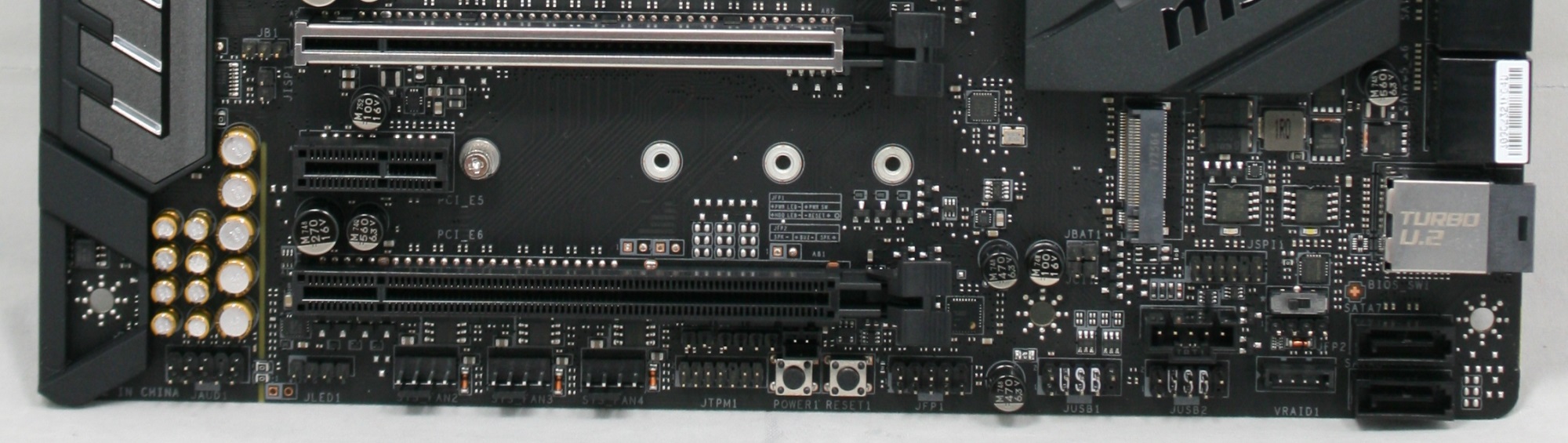
To the right of the PCIe slots sit the chipset and chipset heatsink. Below that are the two BIOS chips and a switch for choosing which BIOS to run off of. It is always good to have a second BIOS to fall back on in case of a flashing error, or if it gets corrupted with overclocking. The SLI Plus has a BIOS Flashback feature which allows flashing the BIOS without a CPU installed.
| MSI X299 SLI Plus CPU PCIe Layout |
|||||||
| 44-Lane 1/2-Way |
44-Lane 3-Way |
28-Lane 1/2-Way |
28-Lane 3-Way |
16-Lane 1-Way |
16-Lane 2-Way |
16-Lane 3-Way |
|
| PCIe 1 | @x16 | @x16 | @x16 | @x16 | @x8 | @x8 | @x8 |
| PCIe 4 | @x16 | @x16 | @x8 | @x8 | x4 or x8 | @x8 | @x4 |
| PCIe 6 | - | @x8 | - | @x4 | x4 or x0 | - | @x4 |
| PCIe 3 - PCH Shares with U.2 |
x4 | x4 | x4 | x4 | x4 | x4 | x4 |
| SLI | Yes | Yes | Yes | 2-Way | - | Yes | No |
| Crossfire | Yes | Yes | Yes | Yes | Yes | Yes | Yes |
The only device which will affect slot availability will be U.2 devices as it shares bandwidth with the third PCIe slot (x4). The slot configuration is such that there is room for a triple slot video cards when running in slots one and four (the two reinforced slots).
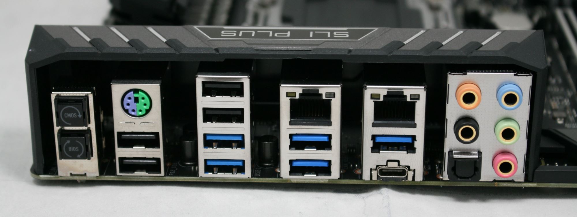
The back panel IO area is of standard fare. From left to right we see the Clear CMOS button and BIOS Flashback+ button, a combination PS/2 port on top of two USB 2.0 ports, and another stack with two more USB 2.0 ports and USB 3.1 (5 Gbps) ports. We get two Intel NICs with one on top of two USB 3.1 (5 Gbps) ports while the other on the right sits above the USB 3.1 (10 Gbps) Type-A and Type-C ports. The audio stack is 5 plug and optical SPDIF out. I would have preferred to see the USB3.1 (10 Gbps) Type-A port a different color in order to differentiate it from the others USB 3.1 (5 Gbps) ports sharing the same space.


In The Box
We get the following:
- User Guide, Memory Installation, and Quick Install Guides
- Driver Disk
- Back Panel IO Shield
- 2x SATA 6 Gbps Cables
- MSI SLI HB Bridge

The included accessories should be what users need to get started. Included are the driver disk (which in my case didn't seem to work), two SATA cables, the back panel IO plate, and a 2-way HB SLI bridge. Also included are the User Guide, Quick Install Guide, and memory installation notice. Two SATA cables is a low amount, but is part of the lower cost of the SLI Plus range. It might also be indicative of the update of M.2 drives, which do not require SATA cables.


20 Comments
View All Comments
Vatharian - Wednesday, November 29, 2017 - link
Why, why manufacturers won't let the U.2 die? We are already past SATA Express, and now this. I get it, it's one of the most popular connectors to connect SAS backplanes, and most of HBAs and RAID controllers do use it, but please, let it die in desktop space. If anything SFF8087 should remain, as SFF-8639 (U.2) is much flimsier and easier to break.Also, we already have far superior standard just behind the corner, in the form of OCuLink.
peterfares - Wednesday, November 29, 2017 - link
Why not have it there though? X299 is a prosumer platform, they may want to use U.2 drives.Lolimaster - Wednesday, November 29, 2017 - link
x399 laughs at X299 being called "prosumer" 44pci-e lanes vs 64 pci-e lanes, bootable nvme raid support.BillyONeal - Wednesday, November 29, 2017 - link
I'm a "prosumer" who built both X299 and X399 boxes and couldn't care less about those things. Compiler want MOAR CORRRREEEESSSSSSdrajitshnew - Friday, December 1, 2017 - link
Why call it a prosumer product when it doesn't have ANY m2/u2 connected to the processor?andychow - Wednesday, November 29, 2017 - link
Doubtful it will disappear. With Optane coming out with only a U.2 connector on the SSD format, it rather insured that U.2 will grow in demand.BillyONeal - Wednesday, November 29, 2017 - link
The 750 was also like that but didn't spur demand for U.2. The add-in cards are just fine.Dr. Swag - Wednesday, November 29, 2017 - link
Could you guys do some better vrm testing? X299 vrms have been a hot topic (pun intended) due to Skylake X drawing a lot of power when OCed and because of the addition of up to 18 cores. Some vrms get quite toasty under load so if you guys had good vrm temp measurements and perhaps even measurements on voltage ripple and stuff coming out of the vrm that would be awesome.vgray35@hotmail.com - Wednesday, November 29, 2017 - link
And let's not forget measurement of VRM power efficiency to compare the quality of VRMs across motherboards!Lolimaster - Wednesday, November 29, 2017 - link
Just but Threadripper and forget about those problems.