MSI 875P Neo-FIS2R (875P): Our favorite thus far
by Evan Lieb on May 6, 2003 12:01 AM EST- Posted in
- Motherboards
MSI 875P Neo-FIS2R: Board Layout
In general we were very pleased with the 875P Neo-FIS2R's layout.
We were pleased to see the ATX (20-pin) connector positioned towards the top and on the right-hand side of the PCB. Locating the ATX connector here is good for case organization and convenience as the thick wires won't obstruct the installation/uninstallation of the CPU HSF (especially bigger ones) or the North Bridge heatsink, as well as any other components that you may decide to modify or uninstall in that area. If we had to nitpick, we would have preferred that the ATX connector were just a tad higher up on the board by about another inch.
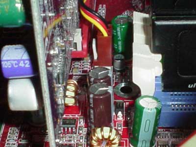
Unfortunately the ATX12V connector is located over on the left-hand side of the PCB near the I/O ports. We aren't at all fond of this location because the ATX12V cable from a standard PSU will run directly over the CPU HSF, making it impossible to uninstall this HSF until you unhook the ATX12V line. Of course, higher quality PSUs have extra long ATX12V and ATX cables, so this won't be an issue with these particular PSUs.
The Primary and Secondary IDE connectors are placed exactly where we like to see them, on the right-hand side of the PCB to right of the DIMM slots and above the midsection of the motherboard. We've experienced what a hassle it can be to have the Primary and Secondary IDE connectors placed on the lower portion of the motherboard, as it makes it much more difficult for IDE cables to reach to the highest bays of a large-sized ATX case. We're glad MSI decided to put the Floppy connector next to the right of the Primary and Secondary IDE connectors, as the Floppy drive bay location should mitigate any possible cable tangling that could occur with the Primary and Secondary IDE cables.
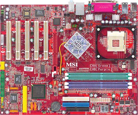
MSI includes an active North Bridge heatsink to cool down the 875P North Bridge. This active heatsink is more than enough to cool the North Bridge; the active heatsink was barely warm to the touch at full load. Interestingly enough MSI decided to add green, blue and red flashing lights to the North Bridge heatsink for users that have see-through cases.
Thankfully MSI places the DIMM connectors far enough away from the AGP slot so that it doesn't become a hassle to uninstall the video card if you want to install or uninstall memory. Those of you that frequently upgrade and maintain your hardware know how annoying cramped DIMM connector space can be, or any cramped space for that matter.
Near the I/O ports are voltage regulator heatsinks that MSI is well-known for using in quite a few of their high-end motherboards. It certainly doesn't seem all that unnecessary as these tiny heatsinks get quite warn to the touch at full load. MSI claims that these heatsinks should aid in overclocking, though we're skeptical of its real-world usefulness.
The location of the USB 2.0 and IEEE 1394 FireWire headers are perfect; there is one USB 2.0 header located at the very bottom edge of the PCB just below the 5th PCI slot. This is excellent positioning as there's basically no chance of your USB 2.0 bracket getting tangled up with any other wires/cables or hardware components. Similarly, there are three IEEE 1394 FireWire headers located just to the right of the USB 2.0 header, and all are located well enough that the FireWire bracket cables won't be obstructing much. Though, we did notice that the FireWire header located closest to the right edge of the board could get tangled with one of the Promise-controlled Serial ATA connectors if you were to use this controller for your Serial ATA hard drive. Otherwise, USB/FireWire header locations are excellent.


1 Comments
View All Comments
Anonymous User - Friday, August 15, 2003 - link
Hold your horses with this board... there are multiple BIOS errors at the moment and MSI are NOT keen to sort them out in a timely manner.Check out the MSI P4 boards (which are flooded with 875P error posts)
http://www.msi.com.tw/program/e_service/forum/boar...
Best of luck!