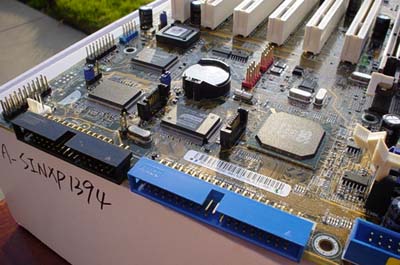
ASUS P4SDX Deluxe: Board Layout
The ASUS P4SDX almost identically mimics the SiS 655 reference board layout. For the most part, this layout isn't exactly ideal in terms of convenience for the system builder and frequent upgrader, as was the case with the MSI 655 Max.
ASUS positions the ATX (20-pin) connector at the very top, middle portion of the PCB, instead of on the left-hand or middle portion of the motherboard that is fairly common nowadays. We like how ASUS positioned the ATX (20-pin) connector on the P4SDX because the thick ATX wires won't obstruct the installation/uninstallation of the HSF, passive North Bridge heatsink or any other components that you may decide to modify or uninstall in that general area. This positioning is most important for PSUs that do not have extra long ATX cables like Enermax or Antec PSUs usually carry.
The ATX12V connector is located at the very top of the PCB to the left of the ATX (20-pin) connector. This is a good position since the vast majority of PSUs have identical length ATX12V cables, and this means that you can tuck the ATX12V cables away from motherboard components. However, we would have like to have seen the ATX12V on the other side of the board and towards the top, that way no tucking is needed.
ASUS places the Primary and Secondary IDE connectors in the perfect location; to the right of the DIMM slots and up the right hand edge of the PCB. The Secondary IDE connector is placed quite high, only about an inch from the very top right-hand edge of the motherboard. This is the ideal place for the Secondary IDE connector for two reasons; 1) it puts it very close to the drive bays so you don't have to worry about your IDE cables being too short and 2) most users have their optical drives connected to the Secondary IDE connector meaning you don't have to cross your Secondary IDE cables over your Primary IDE cables. The IDE RAID connector is also well placed, located at the edge of the board below the AGP slot line and tilted 90 degrees towards the front of the case. This is the best position to have the IDE RAID connector as your hard drives will be very close to the connector. All in all, the IDE connector locations on this board are ideal for users that want a quick install and not have to deal with additional case clutter. Our only complaint is with the Floppy connector. If the Floppy connector and IDE RAID connector switched places, your Floppy cable wouldn't have to maneuver itself as much away from the IDE RAID cable.
Unfortunately, the DIMM connectors are located too close to where our video card is installed. We prefer to see the DIMM connectors about half an inch away from the video card so that we're not forced to uninstall the video card if we want to install or uninstall memory.
One of the other onboard features that ASUS includes on the P4SDX Deluxe (but that has nothing to do with performance) is ASUS's patented EZ Plug technology. EZ Plug is made possible by a standard 4-pin AUX connector, which all modern-day ATX power supplies carry. EZ Plug functions as a replacement for the ATX12V connector that the vast majority of P4 motherboards contain, and that ASUS includes anyway. While not incredibly useful, it's a nice feature to have nonetheless.
FireWire and USB 2.0 headers are located in good positions. The one USB 2.0 header on the PCB is located at the bottom, middle portion of the motherboard. This way, you can use up the last PCI slot with your USB 2.0 bracket and not create clutter around that area. The two red FireWire headers are located directly above the USB 2.0 header by about two inches. This is also a good position, as your FireWire bracket can take up one of the higher PCI slots and not get in the way of anything else, including the Serial ATA connectors.


0 Comments
View All Comments