GIGABYTE Z97X-UD5H Review: Choose Your Storage Option
by Ian Cutress on May 14, 2014 9:00 AM EST- Posted in
- Motherboards
- Intel
- Gigabyte
- Z97
For the first of our Z97 reviews, GIGABYTE sent us its mid-range Z97X-UD5H. This model is designed for the casual enthusiast interested in the higher end of the feature set but not so far in overclocking nor gaming. GIGABYTE has a new color scheme for its channel range, and is aiming for a reasonable $190 price point.
The Z97 Chipset
We covered the nuances of the Z97 chipset in our Haswell Refresh review on Sunday, but the take home message was storage. Z97 allows motherboard manufacturers to use chipset lanes for SATA Express and M.2 ports, bringing PCIe based storage to the desktop platform without the need for a PCIe card. At current, these solutions only provide two lanes of PCIe bandwidth (10 Gbps), which should be 66.67% faster than SATA 6 Gbps, but it all comes down to the controller on the device used. There are currently a few M.2 PCIe x2 drives on the market, mostly SATA based, but zero SATA Express, making the manufactures who invest in these storage technologies waiting for future product.
SATA Express offers the chance for users to implement either SATA or a SATA Express device on the motherboard, however using a SATA Express device removes those two SATA ports out of the equation for other drives.
M.2 (NGFF) drives can come in SATA or PCIe form factors, and as such motherboard manufacturers have the option of providing PCIe only M.2, SATA only M.2, or a slot that will affix to both. Looking at the current Z97 designs, it would seem that most manufacturers are using M.2 as PCIe storage only, making the point moot.
All this allocation comes from somewhere, and the Intel 9-series chipsets support Flex-IO to modify how the PCIe lanes are arranged:
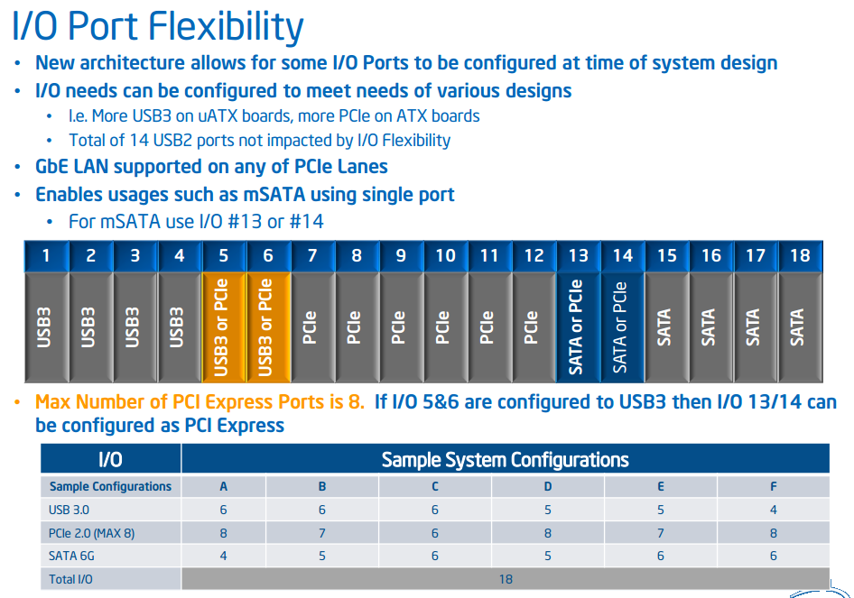
The chipset has access to 18 ports, four of which are USB 3.0, four are SATA 6 Gbps and 6 are PCIe. This leaves two sets of two, the first set can be configured for either USB 3.0 or PCIe, and the second set are either SATA or PCIe, but only a maximum of eight PCIe ports are possible. This is designed as a catch-all interface for different sized motherboards, where some can use more PCIe lanes, others can use more USB 3 ports, and so on. Depending on how SATA Express is implemented, these lanes can be used and abused for storage purposes.
The Z97X-UD5H we are reviewing today has a SATA Express port on the motherboard, but unfortunately we do not have the tools to test it. GIGABYTE has used SATA ports from the chipset and included a SATA controller to offer two more SATA ports in case the SATA Express is in use, allowing six SATA devices in total alongside a SATA Express drive.
GIGABYTE Z97X-UD5H Overview
Motherboard design from the big four has gotten to a point where good is now average and excellent is the new good. The new battlegrounds include specific functionality, aesthetics, improving over the basics and user interaction. With Z87 we saw each of the manufacturers pick design philosophies for their ranges, and now with 9-series we are seeing the next iteration of those philosophies. For GIGABYTE’s channel motherboard line, the Ultra Durable moniker is the leading message, attempting to portray the use of higher quality components. This means the use of International Rectifier designs on the power delivery of most products, as well as per-port USB fusing, 15 micron gold in the socket and 10K black capacitors among others.
GIGABYTE is keen to promote the UD5H with both SATA Express and M.2 support. Most manufacturers are going to have a price point which combines these two features on a product rather than being selective having one of the other, and for the UD5H $190 does get both. One issue to consider for the manufacturers is that when either one to be used, the cost of the connectors has to be considered. M.2 uses a raised onboard connector whereas SATA Express is more a SATA-derived port. While talking about $0.05 here and there does not sound like much, believe me when I say that even these small costs are considered in the design process. These also introduce an element of chipset routing design, as using PCIe lanes for extra storage might move them away from other features. The UD5H gets around this by using a PCIe switch, meaning the user has a choice of either M.2, SATA Express, or two SATA 6 Gbps ports.
The Z97X-UD5H goes along the path of adding features respective to its price point: power/reset buttons with a two digit-debug, voltage measure points, SATA Express, an additional SATA 6 Gbps controller, a SATA power connector for VGA power, dual NICs (one Atheros Killer, one Intel), six fan headers, a USB hub for 8 USB 3.0 ports total, a SATA controller for 8 SATA 6 Gbps ports total and an x8/x4/x4 PCIe layout.
The BIOS gets a new frontage in the form of a ‘Startup Guide’, however there are still some BIOS user experience issues to iron out. Z97 also offers GIGABYTE users a chance to sample the second revision of its new operating system software. APP Center was a little rough around the edges during Z87, but the new solution on Z97 is more thought out and better planned, making it both easier to use and intuitive.
While the supplied audio drivers give a distortion issue at 100% volume, this should be fixed with a driver update. The UD5H is the only Z97X motherboard in our testing to be under 12 seconds POST time at default, and also is in the low band for power consumption. CPU performance is commensurate with the other Z87/Z97 motherboards we have tested in our 2014 benchmark suite, and manual overclocking pushed our sample to 4.6 GHz. Automatic overclocking was a little too aggressive on the voltage, causing overheating on our i7-4770K.
We still need to get the lay of the land with a few more Z97 reviews, however at $190 the UD5H was easy enough to use and there were plenty of positive design inferences indicating that GIGABYTE is certainly putting a lot of time and effort into their product.
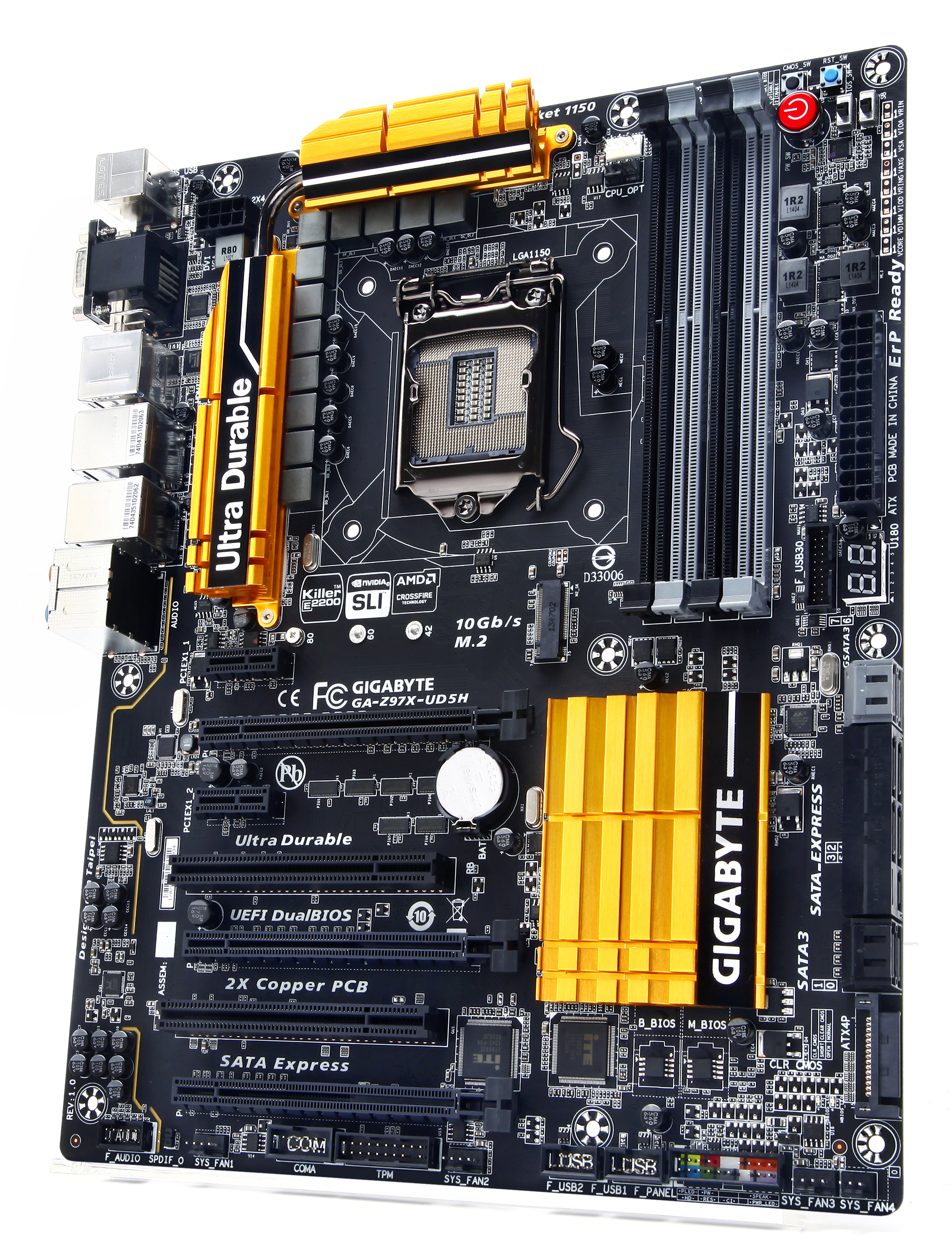
Visual Inspection
GIGABYTE in previous years has been known for its separate color schemes whereby the overclock line goes orange, gaming goes green, the low end channel is blue and the UD series is an almost free-for-all. Despite the backlash of gold colored motherboards in the last generation, it would seem that certain sections of the motherboard industry are at least warming to them, using a gold/mustard yellow hybrid with some degree of metallic character.
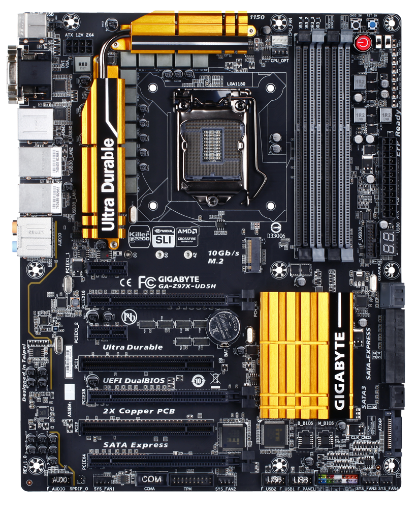
At first glance, the motherboard looks fairly empty. The old days of very busy motherboards with components all over the place have been relegated to the retirement home and the result is a more aesthetically pleasing product. Using a bright, metallic color on the heatsinks allows some of the areas to brighten up when lights are shining, which may help.
The socket area conforms to Intel specifications, with the chokes on two of the edges and DRAM slots on another. The power delivery heatsink, covering 40A rated IR3553 ICs, is slightly further back allowing larger coolers to take center stage. We have direct access to two of the fan headers on board, called CPU and CPU_OPT just above the socket. These are designed to cater for liquid loop coolers, where the pump is kept on by the CPU_OPT fan header. The other four fan headers are all at the bottom of the board, one of them three-pin and the rest are four-pin.
The DRAM slots are of alternating color, mimicking the SATA ports which also offer a black/grey combination to identify those powered by the chipset or controller. Moving clockwise around the motherboard, in the top right hand corner is a big red power switch flanked by two buttons for reset and clearing CMOS. There are also two switches next to these buttons – one for implementing DualBIOS (in case one BIOS is corrupted and needs to be reflashed with the other) and one for selecting which BIOS chip to use. For overclockers that might have multiple BIOS firmware versions for different benchmarks, this makes handing BIOSes a lot easier. Also for the overclockers are a series of voltage read points just above the 24-pin ATX power connector.
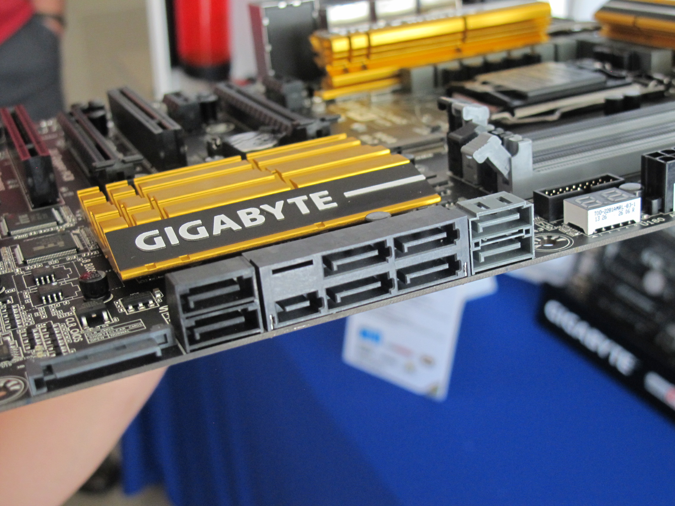
Beside the two-digit debug is a USB 3.0 header from the chipset, and then we come to the SATA ports. The two at top in grey are powered by a Marvell 88SE9172 controller, whereas the other six come from the chipset. The central column also contains the SATA Express connector. In order to better understand the SATA configuration, I pulled out the chipset diagram from the manual:
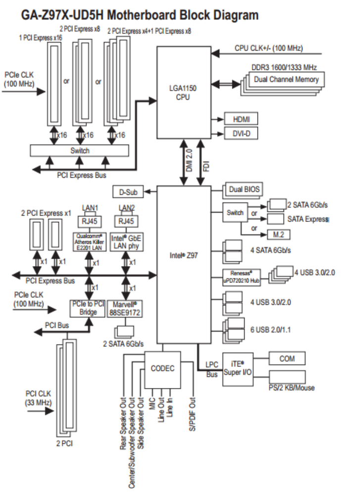
The important section is on the right, under dual BIOS. Here we have a switch where the user can have either two SATA ports, SATA Express or M.2. This switch happens automatically based on the detection during POST, which removes any form of hot plug capabilities.
Below the SATA ports is a SATA power connector, used for supplying more power to the PCIe slots in case a user wants to implement a 3x CrossFire solution.
The bottom of the motherboard contains the four aforementioned fan headers, two USB 2.0 headers, a TPM header, a COM header, the front panel audio header and the front panel header. Interestingly above the USB 2.0 headers are what looks like two SuperIO chips, despite the chipset diagram above only using one. One of these is actually the PCIe to PCI controller, which is surprisingly large for the function it does. I wonder if smaller versions of that IC are available.
The PCIe layout is indicative of a standard three-way PCIe implementation, with GIGABYTE choosing to support the x8/x4/x4 layout from the CPU. Due to the implementation of SATA Express and M.2 on the 9-series chipsets, it would make sense for more motherboards to this layout rather than sacrificing four PCH lanes for a PCIe 2.0 x4 slot. GIGABYTE has flanked this layout with a pair of PCIe 2.0 x1 slots from the PCH and two PCI slots via a bridge chip.
The audio subsystem is built around a Realtek ALC1150, with filter caps, a headphone amp for the rear panel and PCB separation.
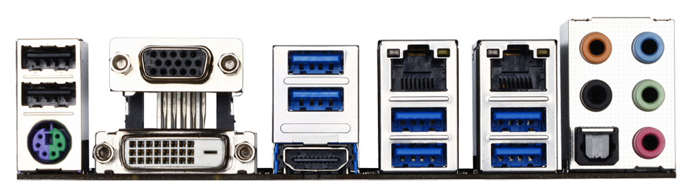
The Rear IO abuses a Renesas USB 3.0 hub to one USB 3.0 port into four, bringing the total number of USB 3.0 ports the motherboard can handle to eight. The data sheet for the hub lists the idle power draw of the hub as 10 mW. Other ports on the rear panel include two USB 2.0 ports, a combination PS/2 port, video outputs (VGA, DVI-D and HDMI), two NICs (one Killer E2201, one Intel I217v) and the audio jacks.
Board Features
| GIGABYTE Z97X-UD5H | |
| Price | Link |
| Size | ATX |
| CPU Interface | LGA-1150 |
| Chipset | Intel Z97 |
| Memory Slots |
Four DDR3 DIMM slots supporting up to 32 GB Up to Dual Channel, 1333-3200 MHz |
| Video Outputs |
VGA (1920x1200 at 60Hz) DVI-D (19200x1200 at 60Hz) HDMI 1.4a (4096x2160 at 24 Hz or 2560x1600 at 60 Hz) |
| Onboard LAN |
Qualcomm Atheros Killer E2201 Intel |
| Onboard Audio | Realtek ALC1150 |
| Expansion Slots |
3 x PCIe 3.0 (x16, x8/x8 or x8/x4/x4) 2 x PCIe 2.0 x1 (PCH) 2 x PCI |
| Onboard SATA/RAID |
6 x SATA 6 Gbps (Chipset), RAID 0/1/5/10 1 x M.2 PCIe x2 (Chipset) 1 x SATA Express (Chipset) Note: M.2, SATA Express and SATA3_4/5 are connected, only one of the set can be used at once 2 x SATA 6 Gbps (Marvell 88SE9172), RAID 0/1 |
| USB 3.0 |
4 x USB 3.0 (Chipset) [1 header,2 back panel] 4 x USB 3.0 (Renesas Hub) [4 back panel] |
| Onboard |
8 x SATA 6 Gbps 1 x SATA Express 1 x M.2 PCIe 1 x USB 3.0 Header 2 x USB 2.0 Headers 6 x Fan Headers 1 x COM Header 1 x TPM Header Power/Reset Buttons Clear CMOS Button Two-Digit Debug 2 x BIOS Switches Voltage Read Points Front Panel Header Front Audio Header |
| Power Connectors |
1 x 24-pin ATX 1 x 8-pin CPU 1 x SATA (for PCIe) |
| Fan Headers |
1 x CPU (4-pin) 1 x CPU_OPT (4-pin) 4 x SYS (3 x 4-pin, 1 x 3-pin) |
| IO Panel |
1 x Combination PS/2 2 x USB 2.0 VGA DVI-D HDMI 6 x USB 3.0 2 x Ethernet (ALC1150) Audio Jacks |
| Warranty Period | 3 Years |
| Product Page | Link |
Users might notice that the Z97 motherboards will support higher rated memory, with small generational improvements in design allowing for 3200 MHz with the UD5H. The Killer E2201 NIC is advertised as a network port that prioritizes various traffic, although our sources put the E2201 as a normal Atheros NIC with Killer software in one sales package. This is chosen over buying a Broadcom NIC and licensing something like cFos, which might be more expensive and/or offers fewer advertising opportunities around the branding. Personally I would have preferred one or two of the four fan headers on the bottom of the motherboard to be nearer the top, allowing cases with fans on the rear and top to be easily accommodated.


53 Comments
View All Comments
The_Assimilator - Thursday, May 15, 2014 - link
A: By that argument every chipset ever made should still support ISA.B: The Flex IO diagram on this very page specifically states "Total of 14 USB2 ports". I'm reading that as being a constant entirely independent of the number of USB 3.0 ports, but if you have any literature to contradict that, I'd be appreciative if you could link it.
repoman27 - Thursday, May 15, 2014 - link
Not sure I follow your logic. USB is probably the most used feature of a modern chipset (I suppose SATA probably gives it a run for its money though). Take a look at any USB 3.0 connector and you'll find 5 contacts which correspond to the SuperSpeed transmit and receive signaling pairs and ground, and then 4 more that carry the USB 2.0 signal and Vbus. This is how USB 3.0 achieves SuperSpeed while maintaining backwards compatibility, and the signals all need to come from somewhere.Intel hasn't posted datasheets for the 9 series chipsets yet, but there really isn't a heck of a lot of difference between them and the 8 series (in fact they're all currently listed in ARK under the "Products (Formerly Lynx Point)" heading). In the 8 series datasheet [ http://www.intel.com/content/dam/www/public/us/en/... ], however, Intel states: "xHCI USB controller provides support for up to 14 USB ports, of which six can be configured as SuperSpeed USB 3.0 ports." Intel also includes this additional note: "Some USB 3.0 motherboard down devices do not require support for USB 2.0 speed and it is possible to route only the SuperSpeed signals, as allowed by the USB 3.0 specification. In this special case, USB 2.0 and USB 3.0 signals will not need to be paired together, thereby allowing support for more than 14 USB connections."
Interestingly, although the PCH package only provides connections for 14 USB 2.0 signals, those signals can come from either the newer xHCI or the two legacy EHCI controllers which are still present on the chip.
DanNeely - Thursday, May 15, 2014 - link
Am I correctly understanding that as saying that by routing the signals separately you could create a USB3 only port that's not back compatible with USB 1/2?repoman27 - Thursday, May 15, 2014 - link
You're not allowed to do that according to the USB 3.0 Specification, but let's say you had an on board card reader that had a SuperSpeed USB interface, then you wouldn't necessarily be required to route a USB 2.0 signal to it as well and could use that signal for something else instead.repoman27 - Thursday, May 15, 2014 - link
If all the high speed signaling ports were Flex I/O ports, everyone who purchased a PC or motherboard based on that platform would be paying for an insanely large PCIe 2.0 switch with 18 downstream lanes/ports, an 18-port xHCI, and an 18-port SATA 6Gb/s controller plus 18 separate muxes to steer the desired signals to each port. I'm sure Intel would be happy to sell all that to the OEMs instead of just letting them use discrete controllers, but I seriously doubt it would end up lowering the BOM cost any. Flex I/O is just a way to keep the PCH package size down by steering features to a reduced number of balls. I'd rather be able to actually utilize all of the controllers I'm paying for.Not all of the chipsets offer 14 USB ports, and not all of the available USB ports are necessarily routed to external connectors or headers on the logic board. Some of them are used to connect devices on the motherboard itself or other embedded features. Also, since this many ports have been available since the 5 Series, Intel can't exactly regress the feature set while AMD is still offering 14 USB ports.
KAlmquist - Thursday, May 15, 2014 - link
With the current "Flex IO" design, Intel implemented 20 high speed controllers (8 PCIe, 6 SATA, and 6 USB 3.0), but only provided pinouts for 18 of them, meaning that two controllers sit unused. To provide full I/O flexibility, Intel would have to implement 54 controllers (18 of each type), 36 of which would be unused. It sounds like a waste of silicon to me.gloinsir - Wednesday, May 14, 2014 - link
The Rear IO abuses a Renesas USB 3.0 hub to one USB 3.0 port into four, bringing the total number of USB 3.0 ports the motherboard can handle to eight.Oh the poor Renasus abuse.
celestialgrave - Wednesday, May 14, 2014 - link
I guess I don't really see the need for wifi built into my desktop motherboard. I'd rather have the dual NICs. But I guess I can see the advantage when it comes to building a computer for mom or grandma.Ian Cutress - Wednesday, May 14, 2014 - link
If you have a family, more often than not there is a central WiFi router in the house connecting to everyone. If the house/flat isn't all layed out in RJ-45, then if everyone has a computer it has to get the WiFi signal for connections. For example, I have my NAS connected via ethernet to the router, but the three systems in my office are all connected via WiFi, as well as the HTPC in the front room.plopke - Wednesday, May 14, 2014 - link
I am still confused about what PCI-Express and M.2 supposed to be in the end for like a regular consumer? One time i read M.2 stuff and pice express will use the same protocl then other times i read articles like this that they wont work together , etcAny change anyone has some googlde docs spreadsheet that show a table like
connecter type motherboard | protocol | protocol max speed | connecter type SSD | speed SSD | max theorictal performance | compatible