Gigabyte Z77X-UP4 TH Review: Thunderbolt Times Two
by Ian Cutress on September 17, 2012 11:00 AM EST- Posted in
- Motherboards
- Gigabyte
- Z77
- thunder
Gigabyte Z77X-UP4 TH In The Box
The Gigabyte naming range covers anything from a UD2 up to a UP7 and all in-between. The big numbers usually indicate a higher level of product, and if any of the recent reviews have shown is that moving from a UD4 to a UD5 (or a UP4 to a UP5) is actually a big jump in terms of functionality, design, and included extras. With the Z77X-UP4 TH, we get the following:
Driver CD
User Manual
Rear IO Shield
Four SATA Cables
Flexi SLI Bridge
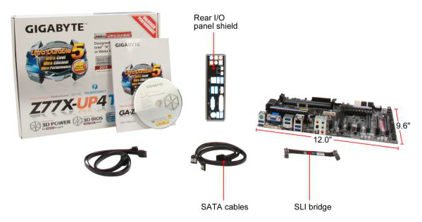
If I saw the contents of this package without the board or model in front of me, I would have paired the extras squarely inside a UD2 or UD3 package. For it to also be in the UP4 has taken me aback. No mention of a USB 3.0 panel, or an appropriate SLI bridge for 3-way. This is a Thunderbolt box – perhaps even a Thunderbolt cable or peripheral would have been some sweetening. My comments earlier regarding being built to a price ring true here as well.
Voltage Readings
After my first publication of OCCT voltage readings, a few readers responded with a more in-depth reasoning behind some of the results we were seeing. With this in mind, I would like to re-describe what we are doing with this test, and how it comes about.
Much of what an enthusiast overclocker does is monitor CPU temperature and voltage. Whatever settings a user places in the BIOS or OS is at the mercy of the motherboard - in terms of actually setting the values and reporting the values back. As an enthusiast, we have to rely on what readings we get back, and hope that motherboard manufacturers are being honest with their readings.
Take CPU voltage. What we as a user see in CPU-Z or OCCT is a time-averaged value that hides voltage ripple (if any) for power delivery. It is very easy for a motherboard manufacturer to hide this value, or to disregard slight deviations and report a constant value to the user. The CPU voltage reading can be taken at a variety of places on the power plane, which can vary between motherboards and manufacturers, meaning that each reading is essentially not comparable with the other. Nevertheless, as an enthusiast, we will constantly compare value A with value B.
Whether or not I can achieve 4.7 GHz with 1.175 volts on a particular board is inconsequential - your motherboard may perhaps produce the same result with a reading at 1.200 volts. The only way to test the actual value is with consistent methodology is via an oscilloscope connected to similar points on each board. This may sound like taking an OCCT reading is therefore redundant.
However, motherboards have settings relating to load line calibration. As load is applied to the CPU, the voltage across the processor decreases (VDroop). Load Line calibration essentially attempts to control this level of droop, by increasing voltage when voltage drops are detected away from a fixed value. Manufacturers have different ideas on how to modify LLC with respect to load, or whether the level of modification should be controlled by the user. Some manufacturers offer the option at a variety of levels, such that overclockers can be sure of the applied setting (even if it increases peak voltage, as explained by AnandTech in 2007).
By doing a full load OCCT test, we are essentially determining both how aggressive the motherboard is reporting the CPU voltage under load and how aggressive load line calibration is performing (from the point of view of the user without an oscilloscope or DVM). If someone has one of the motherboards we have tested and you have a different one, variations in load voltage should describe the offset you may require for overclock comparisons.
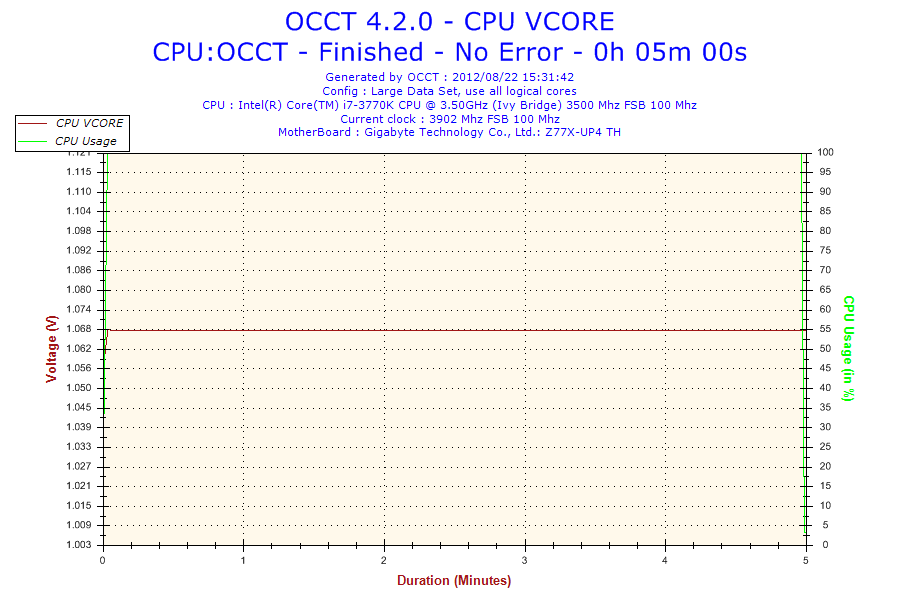
CPU voltage readings on Gigabyte Z77 motherboards have been odd as of late. Initially we thought that Gigabyte was manipulating the voltage readings from the board to the operating system to give a semblance of improved usage. Then on the Z77MX-D3H, even in overclocked scenarios the voltage reading was the same value as the stock reading. This made us caution a little more – what sort of games or tricks were being played? Then on the UD5H we noticed that on boards where the voltage does change under OC, while at at stock the voltage reaching can actually change, although Gigabyte has set the reading to change with a granularity of 0.01 volts. On all other motherboards we test, OCCT shows variations when the voltage fluctuates by ~0.004 volts – even though OCCT is itself a time smoothed average, we expect to see some variation. The results of this are two fold – the Gigabyte boards do vary in the voltage but they do not want the user to know about it, but if the improved power delivery of the Ultra Durable 5 system results in less ripple, why set the minimum reporting variation so high? This means that as reviewers we cannot comment on how stable the load line calibration is if no variation is seen at all. As a result, I am unwilling to add voltage values in our comparison table for boards like this, as it could hide the true representation of default LLC and load voltages. Especially as the load voltage reported under overclocking was the same as reported under stock – 1.068 volts. This means the value is being manipulated between the CPU and the OS at the BIOS level, which should never be the case.


15 Comments
View All Comments
IanCutress - Monday, September 17, 2012 - link
I have access to a TB device, but it is only the two-bay Little Big disk with a pair of Intel Drives. Can't really stress the TB implementation in terms of peak speeds, and in our copy test it can get anything from 1.1 seconds to 3.3 seconds depending on if the wind is blowing, or the tides are in (very unpredictable).When I can get a 4-bay TB device in, I will fill it with 500MB/s+ SSDs and get down to testing. Unless there is a specific test you would like me to do (4K et al).
Ian
repoman27 - Monday, September 17, 2012 - link
I am very curious about a couple points, however they are not the easiest scenarios to test.Firstly, GIGABYTE depicts the ability to support a total of 12 connected Thunderbolt devices plus 2 displays, or 6 devices AND 1 display per port. [ http://www.gigabyte.com/microsite/306/images/thund... ] This seems to fly in the face of what we have been told by Apple and Intel about supported topologies, i.e. "up to a total of 6 devices, including up to 2 high resolution DisplayPort v1.1a displays". Can a single Cactus Ridge DSL3510L really handle that many devices? Is there some difference in implementation between Windows and Mac OS?
GIGABYTE also claims a full 10 Gbps of PCIe bandwidth from each port. Now I would also doubt that claim, and in the article you indicated this wasn't happening with a single DSL3510L. However, Anand achieved 1380 MB/s by using both Thunderbolt ports during his review of the MBPR, which also uses just one DSL3510L controller. Now ultimately this controller is bound by its PCIe 2.0 x4 back end, which should limit it to around 1600 MB/s of payload throughput, but breaking the 1000 MB/s barrier would seem to imply that there is more than one PCIe to Thunderbolt protocol adapter in these Cactus Ridge chips. This would be significant if true. Any chance you could lean on it hard enough to find out?
goinginstyle - Monday, September 17, 2012 - link
I agree about the need for TB testing as I have had nothing but issues with this board and a Seagate GoFlex attached on one port and a Apple TB 27" monitor on the other port. The monitor will flicker badly at times (does not happen on a competing board and a MacBook Pro) while the Seagate drive will "disappear" and requires a power on/off before being recognized again.thewhat - Tuesday, September 18, 2012 - link
It would be great if you could test with Speedfan whether the fan speed can be controlled independently for every header.NiggaASD - Sunday, December 9, 2012 - link
Ian, I think you are wrong about Gigabyte manipulating CPU voltage readings. The voltage reading 1.068 V is probably not CPU vcore, it could be VTT(VCCIO) voltage. It is known that some GB motherboards have this "feature", that they show VTT voltage in CPU-Z. For example, my GA-P67A-UD3P-B3 board shows 1.092 V in CPU-Z as vcore when I have set VTT to 1.1 V in BIOS.