Intel's SSD 910: Finally a PCIe SSD from Intel
by Anand Lal Shimpi on April 12, 2012 3:00 AM EST- Posted in
- Storage
- SSDs
- Intel
- Intel SSD 910
Solid state storage has quickly been able to saturate the SATA interface just as quickly as new standards are introduced. The first generation of well-built MLC SSDs quickly bumped into the limits of 3Gbps SATA, as did the first generation of 6Gbps MLC SSDs. With hard drives no where near running out of headroom on a 6Gbps interface, it's clear that SSDs need to transition to an interface that can offer significantly higher bandwidth.
The obvious choice is PCI Express. A single PCIe 2.0 lane is good for 500MB/s of data upstream and downstream, for an aggregate of 1GB/s. Build a PCIe 2.0 x16 SSD and you're talking 8GB/s in either direction. The first PCIe 3.0 chipsets have already started shipping and they'll offer even higher bandwidth per lane (~1GB/s per lane, per direction).
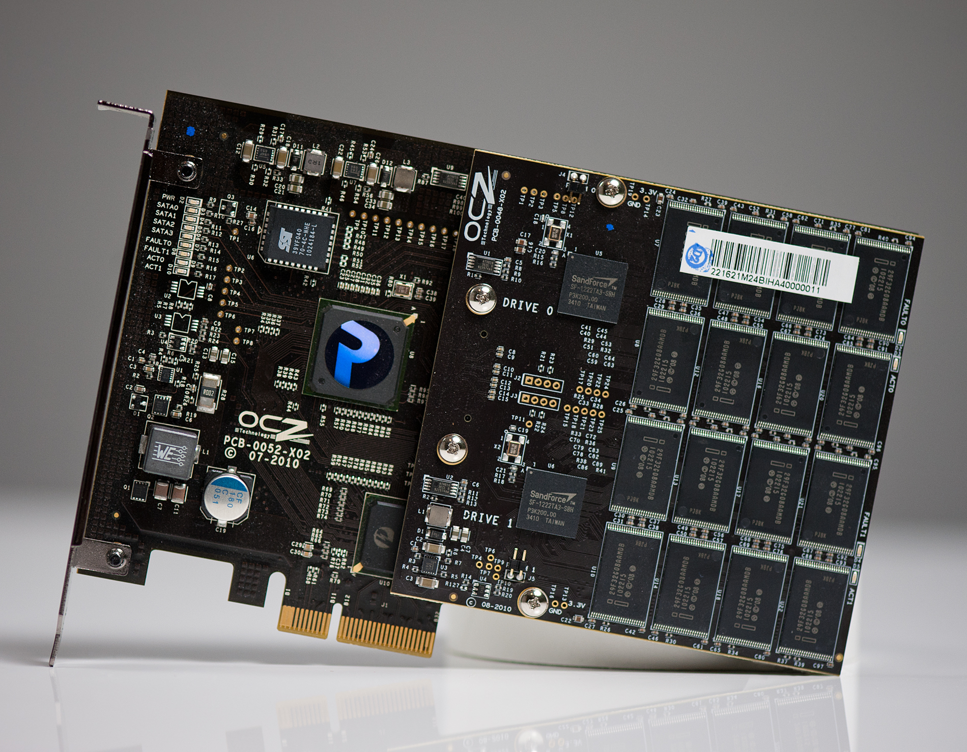
OCZ's RevoDrive X2 PCIe SSD
PCI Express is easily scalable and it's just as ubiquitous as SATA in modern systems, it's a natural fit for ultra high performance SSDs. While SATA Express will hopefully merge the two in a manner that preserves backwards compatibility for existing SATA drives, the server market needs solutions today.
In the past you needed a huge chassis to deploy an 8-core server, but thanks to Moore's Law you can cram a dozen high-performance x86 cores into a single 1U or 2U chassis. These high density servers are great for compute performance, but they do significantly limit per-server storage capacity. With the largest eMLC drives topping out at 400GB and SLC drives well below that, if you have high performance needs in a small rackmount chassis you need to look beyond traditional 2.5" drives.
Furthermore, if all you're going to do is combine a bunch of SAS/SATA drives behind a PCIe RAID controller it makes more sense to cut out the middleman and combine the two.
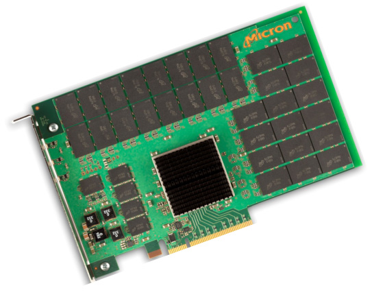
Micron's P320h
We've seen PCIe SSDs that do just that, including several from OCZ under the Z-Drive and RevoDrive brands. Although OCZ has delivered many iterations of PCIe SSDs at this point they all still follow the same basic principle: combine independent SAS/SATA SSD controllers on a PCIe card with a SAS/SATA RAID controller of some sort. Eventually we'll see designs that truly cut out the middlemen and use native PCIe-to-NAND SSD controllers and a simple PCIe switch or lane aggregator. Micron has announced one such drive with the P320h. The NVMe specification is designed to support the creation of exactly this type of drive, however we have yet to see any implementations of the spec.
Many companies have followed in OCZ's footsteps and built similar drives, but many share one thing in common: the use of SandForce controllers. If you're working with encrypted or otherwise incompressible data, SandForce isn't your best bet. There are also concerns about validation, compatibility and reliability of SF's controllers.
Intel's SSD 910
Similar to its move into the MLC SSD space, Intel is arriving late to the PCIe SSD game - but it hopes to gain marketshare on the back of good performance, competitive pricing and reliability.
The first member of the new PCIe family is the Intel SSD 910, consistent with Intel's 3-digit model number scheme.
| Enterprise SSD Comparison | ||||||
| Intel SSD 910 | Intel SSD 710 | Intel X25-E | Intel SSD 320 | |||
| Interface | PCIe 2.0 x8 | SATA 3Gbps | SATA 3Gbps | SATA 3Gbps | ||
| Capacities | 400 / 800 GB | 100 / 200 / 300GB | 32 / 64GB | 80 / 120 / 160 / 300 / 600GB | ||
| NAND | 25nm MLC-HET | 25nm MLC-HET | 50nm SLC | 25nm MLC | ||
| Max Sequential Performance (Reads/Writes) | 2000 / 1000 MBps | 270 / 210 MBps | 250 / 170 MBps | 270 / 220 MBps | ||
| Max Random Performance (Reads/Writes) | 180K / 75K IOPS | 38.5K / 2.7K IOPS | 35K / 3.3K IOPS | 39.5K / 600 IOPS | ||
| Endurance (Max Data Written) | 7 - 14 PB | 500TB - 1.5PB | 1 - 2PB | 5 - 60TB | ||
| Encryption | - | AES-128 | - | AES-128 | ||
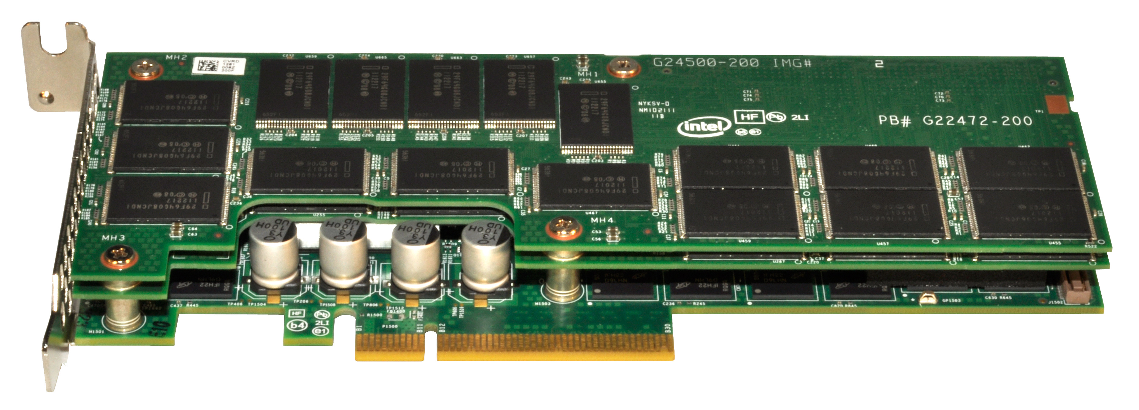
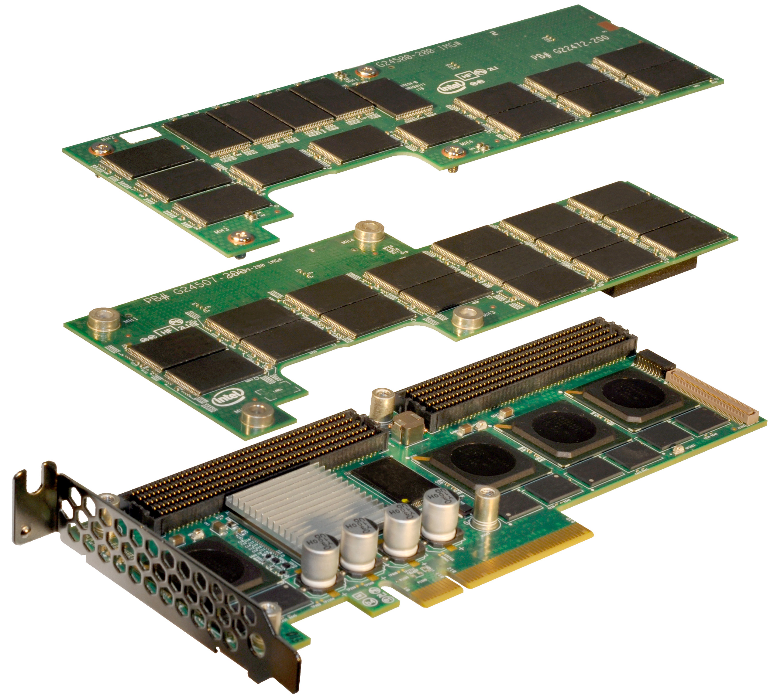
The 910 is a single-slot, half-height, half-length PCIe 2.0 x8 card with either 896GB or 1792GB of Intel's 25nm MLC-HET NAND. Part of the high endurance formula is extra NAND for redundancy as well as larger than normal spare area on the drive itself. Once those two things are accounted for, what remains is either 400GB or 800GB of available storage.
The 910's architecture is surprisingly simple. The solution is a layered design composed of two or three boards stacked on one another. The first PCB features either two or four SAS SSD controllers, jointly developed by Intel and Hitachi (the same controllers are used in Hitachi's Ultrastar SSD400M). These controllers are very similar to Intel's X25-M/G2/310/320 controller family but with a couple of changes. The client controller features a single CPU core, while the Intel/Hitachi controller features two cores (one managing the NAND side of the drive while the other managing the SAS interface). Both are 10-channel designs, although the 910's implementation features 14 NAND packages per controller.
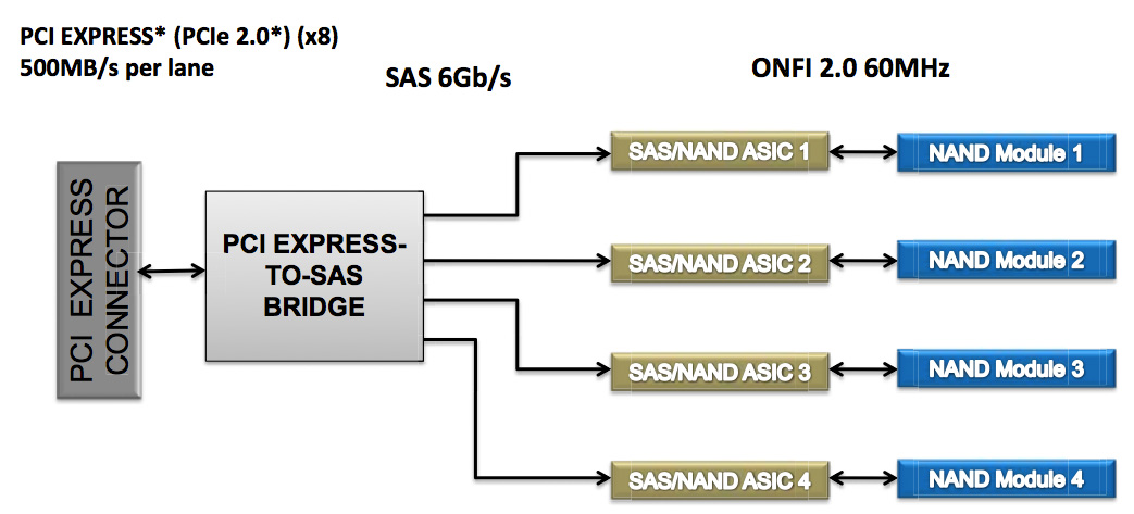
In front of the four controllers is an LSI 2008 SAS to PCIe bridge. There's no support for hardware RAID, each controller presents itself to the OS as a single drive with a 200GiB (186GB) capacity. You are free to use software RAID to aggregate the drives as you see fit but by default you'll see either two or four physical drives appear.
The second PCB is home to 896GB of Intel's 25nm MLC-HET NAND, spread across 28 TSSOP packages. The third PCB is only present if you order the 800GB version, and it adds an extra 896GB of NAND (another 28 packages). Even in a fully populated three-board stack, the 910 only occupies a single PCIe slot.
The 910's TDP is set at 25W and requires cooling capable of moving air at 200 linear feet per minute for proper operation.
The use of LSI's 2008 SAS PCIe controller makes sense as there's widespread OS support for the controller, in many cases you won't need to even supply a 3rd party driver. The 910 isn't bootable, but I don't believe that's much of an issue as you're more likely to deploy a server with a small boot drive anyway. There's also no support for hardware encryption, a more unfortunate omission.
Intel's performance specs for the 910 are understandably awesome:
| Intel SSD 910 Performance Specs | ||||
| 400GB | 800GB | |||
| Random 4KB Read (Up to) | 90K IOPS | 180K IOPS | ||
| Random 4KB Write (Up to) | 38K IOPS | 75K IOPS | ||
| Sequential Read (Up to) | 1000 MB/s | 2000 MB/s | ||
| Sequential Write (Up to) | 750 MB/s | 1000 MB/s | ||
Intel's specs come from aggregating performance across all controllers, but you're still looking at a great combination of performance and capacity. These numbers are applicable to both compressible and incompressible data.
The 910 will ship with a software tool that allows you to get even more performance out of the drive (up to 1.5GB/s write speed) by increasing the board's operating power to 28W from 25W.
| Intel SSD 910 Endurance Ratings | ||||
| 400GB | 800GB | |||
| 4KB Random Write | Up to 5PB | Up to 7PB | ||
| 8KB Random Write | Up to 10PB | Up to 14PB | ||
The 910 is rated for up to 2.5PB of 4KB or 3.5PB of 8KB random writes per NAND module (200GB).
The pricing is also fairly reasonable. The 400GB model carries a $1929 MSRP while the 800GB will set you back $3859, both come in below $5/GB. Samples are available today, with the first production of Intel's SSD 910 available sometime in the first half of the year.
| Intel SSD 910 Pricing | ||||
| 400GB | 800GB | |||
| MSRP | $1929 | $3859 | ||
| $ per GB | $4.8225 | $4.8238 | ||
I have to say that I'm pretty excited to see Intel's 910 in action. Intel's reputation as an SSD maker carries a lot of weight in the enterprise market already. The addition of a high-end PCIe solution will likely be well received by its existing customers and others who have been hoping for such a solution.


71 Comments
View All Comments
vol7ron - Thursday, April 12, 2012 - link
Yes to your points, but no to your last sentence. That's like saying CFM is the same for any case size. Linear feat/minute is more vector-based (directional speed), whereas CFM is volume based. They're both measurements regardless of case size.If you have something spinning really fast, but is really small, it's going to have a fast LFM, but low CFM. Because it has a high LFM, doesn't make it better. Inversely, you can have a really big fan (high CFM), that doesn't spin that fast, much like a ceiling fan. It generally doesn't blow fast enough to move paper on a desk, but it does move the air in the room.
So, I'm saying both measurements are important.
tilandal - Thursday, April 12, 2012 - link
Cubic feet are a measure of volume. Linear feet is just feet. Linear feet per second is a measure of air speed. Speed are related by the cross section the air is moving through. A 10CF/M fan blowing through a 1 Square foot opening moves air at 10F/M. If its through a .1 square foot opening its moving 100F/M.vol7ron - Thursday, April 12, 2012 - link
Right, there's a missing order of magnitude (volume).I guess if the fan is blowing the heat away from the device then CFM isn't as important and linear speed makes sense because it's how quickly it can dissipate the surrounding radiated air.
Senpuu - Thursday, April 12, 2012 - link
Volume is not an order of magnitude [ex: 10000 (10^4) is one order of magnitude less than 1000 (10^3)] .As an example, let's say you have a 10CFM mounted over the fitted intake of a closed case with our Intel SSD positioned in front of a 4"x4" exhaust. That's 10 ft^3 of air that is being brought into the case that needs to be exhausted through a 4"x4" hole every minute. That hole is a (1/3ft)^2 or 1/9 ft^2 cross section. 10 ft^3 of air goes through that hole every minute (a measure of volume / time), but it does so at a rate of 90 ft / min (a measure of distance / time). 90 ft/min < 100 ft/min minimum in the SSD spec, so you'd have to increase the fan CFM (by increasing the RPM or replacing the fan) or decrease the exhaust opening to ~3.79"x3.79".
Fans are rated in terms of CFM and not LFM because LFM is a function of system geometry and location whereas CFM is only a function of fan geometry and RPMs. As you said though, local heat transport is best expressed in LFM.
vol7ron - Thursday, April 12, 2012 - link
Volume is an order of magnitude. It's adding a third dimension. For instance, when converting a 4"x4" square (4 sq. in -or- 4 in^2) to a cube (4 cu. in -or- 4 in^3 -or- 4"x4"x4"), the volume is exponentially bigger than the surface area.In math, magnitude is difference in relative size. A 2D figure is an order of magnitude smaller than a 3D figure.
That said, you've given a good example. CFM=LFM x Area; or, Q=V x A. I'm still unsure why LFM is preferred over CFM. However, your last point is incorrect. CFM isn't only for fans, and the rotational velocity of the fan is only one variable that could go into creating air flow. Fan's have fins that are angled and push air, the length and degree of their angle are also very important. So is the material, and it's resistance to the force of air against the fan as it spins.
CFM is the flow rate, which applies to air/water/anything that's 3D. LFM is only the speed (velocity), as you put it, the distance over time. Agh. I give up on understanding the purpose, perhaps because the heat isn't always constant in one part of the board, or to be able to use that figure in other form factors (difference size chips).
FunBunny2 - Thursday, April 12, 2012 - link
-- I'm still unsure why LFM is preferred over CFM.Look at the card. With 3 boards, there's no "volume" to speak of. It needs fast "exhaust" to cool it.
vol7ron - Thursday, April 12, 2012 - link
I think that makes the most sense - how quickly you can displace the air that cushions the board.I was thinking that's a factor in CFM, which it is, but I wasn't thinking about the significance of that factor. That is somewhat bewildering because I even explained it in my ceiling fan example: low velocity, high area - sure you're moving a lot of air in a minute, but between revolutions there is stagnant air.
I apologize - I did not mean to take up all the comment space in what should have been addressed in the forums.
Senpuu - Monday, April 23, 2012 - link
Volume is not an order of magnitude and I have never in my time with the sciences and maths heard it used as such. Cite me any respectable reference where it is used as such and I'll gladly cede the point.And, since we're nitpicking and being technical, my last point is only slightly incorrect, as I should not have used the word 'only'. There are other factors -- such as the rigidity of the blade, which is a function of the geometry and the material properties, as you pointed out -- but the angle, length, etc are all part of the fan geometry, which I stated. And I never said that CFM was only for fans. I did say that fans were rated in terms of CFM though, which is true.
I thought the purpose was clear for LFM...? It's giving you an airflow requirement in order to transport sufficient heat away from the component. When air cooling something, the idea is to bring in cool air from outside the case at a certain temperature and pass it over a hot component, thereby cooling the component and heating the passing air as it gets sent out the exhaust. The only pertinent information they need to tell you is how fast that air in order to accomplish that task (assuming standard room temperature for intake air).
double0seven - Thursday, April 12, 2012 - link
I'm just a 2nd yr college student, and you seem to be an actual engineer of some kind or something, but I notice a couple things wrong with the example you give. First, the SSD is positioned in front of the 4"x4" exhaust hole, and the fan is at the intake. Thus, the 90 ft/min you are calculating only occurs on the outside of the case, not at the heat source in question. However if the fan were simply reversed, your example would be more correct.More important is your proposed solution of reducing the exhaust opening in order to meet the spec. Think about this intuitively; how could that possibly result in more heat dissipation? It may make the math work, but the big picture here is that a certain amount of heat is being generated, and a certain amount of air is needed to dissipate the heat. The spec may be given in LFM, but that's ok, cause you're an engineer, and you know how to convert it to CFM!
Metaluna - Monday, April 16, 2012 - link
Right. The air is only in contact with the heatsink for a short period of time. So there isn't much heat transfer beyond the small boundary layer between the heatsink and the airstream. The size of that boundary layer is a function of the velocity of the air close to the heatsink (I believe this is called the near field in fluid dynamics). The only thing that matters is that, the more frequently you can 'replace' this boundary layer (LFM) with new cold air, the more heat you can remove.So as has already been said, specifying the air velocity, in combination with ambient temperature, is more useful when you are looking at the cooling needs of one specific component in isolation.
Where CFM becomes important is in the bulk movement of the heated air out of the case. If you don't do this, then the ambient case temperature rises. This means the temperature of the air passing over the heatsink rises, and less heat can be removed. There are so many variables introduced here, though, that it's almost a useless spec.