Jasper Is Here: A Look at the New Xbox 360
by Anand Lal Shimpi on December 10, 2008 12:00 AM EST- Posted in
- Smartphones
- Mobile
Jasper Dissection
Taking apart a Jasper is no different than taking apart any other Xbox 360 console, despite the internal changes our original guide still rings true. Remove the HDD, pop off the front faceplate, then the sides, separate the top and bottom of the clamshell, unscrew the motherboard and you're off. Doing so obviously voids your warranty, but given that it's possible to identify your console as a Jasper without ever opening it, you shouldn't have to do any of this.
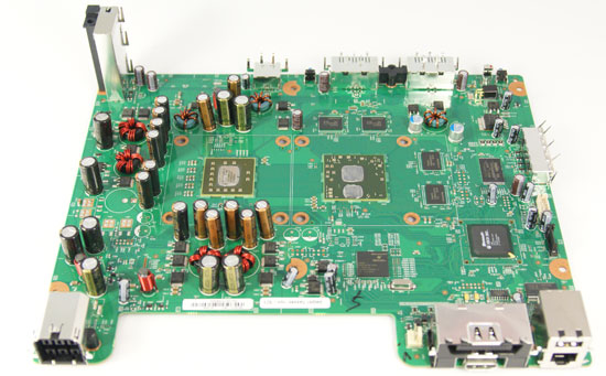
Say Hello to Jasper
Obviously I did, because I wanted to look at the new die-shrunk chips and also to measure die sizes. While I used a ruler to measure the Xenon and Falcon die sizes last year, I wanted to be a bit more accurate this year (after much pleading by Mike Andrawes, our resident Jasper expert) so I used a set of vernier calipers (which is why some of my die measurements are a bit off from the ones I did last year if you're comparing).


The table below shows the die sizes for all of the Xbox 360 generations:
| Xbox 360 Revision | CPU | GPU | eDRAM |
| Xenon/Zephyr | 176mm2 | 182mm2 | 80mm2 |
| Falcon/Opus | 135mm2 | 156mm2 | 64mm2 |
| Jasper | 135mm2 | 121mm2 | 64mm2 |
The new GPU is around 77% of the die area of the old GPU, but the eDRAM appears to be unchanged at 80nm (chalk up the difference of 4mm to differences in measuring the die with a ruler vs. calipers). Compared to the Xenon platform, the GPU is now 66% of the original GPU die size, meaning the GPU actually shrunk more than the CPU in the move to 65nm.
Here's a picture that should put things in perspective though, the chip below is a NVIDIA GeForce 9400M, it's the same IGP that's found in the new MacBooks. It's a 65nm IGP that's got a GPU and North Bridge in it, much like the Xenos GPU in the Xbox 360. Now this is an important comparison because the 9400M is hardly a high end GPU by today's standards yet look at how it dwarfs the Xenos GPU.
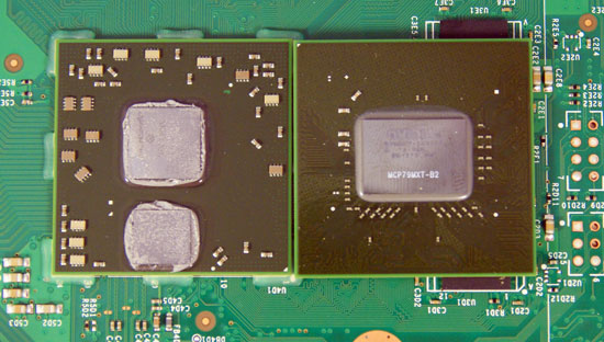
Xbox 360 Xenos GPU (left) vs. NVIDIA GeForce 9400M (right)
Remember that when it was released, the Xbox 360's GPU had raw GPU horsepower somewhere in between an X800 XT and an X1800 series (closer to the latter, although the 10MB eDRAM definitely helped the GPU perform better than its architectural specs alone would allow); today's high end GPUs are around 4x the speed of that.
Microsoft doesn't want to replace the Xbox 360 with a new console until 2011 or 2012, meaning high end PCs will probably have more than six times the graphics horsepower of what's in the Xbox 360. It's possible that once this performance gap gets wide enough we'll see more developers take advantage of the raw horsepower available on PCs, which has traditionally been the case whenever a console got far into its lifespan.
I'm actually a bit surprised that we haven't seen more focus on delivering incredible visuals on PC games given the existing performance gap, but the Xbox 360 as a platform is attractive enough to keep developers primarily focused there.
Added Bonus: 256MB of NAND Flash Standard on Jasper Arcades
An unexpected bonus is that all Jasper based Xbox 360 Arcade systems come with 256MB of NAND Flash on board:
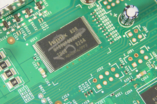
All Xbox 360 Arcade bundles will now come with 256MB of Flash, if you get a non-Jasper you simply get the Flash in the form of a Xbox 360 Memory Unit. The on-board flash is another mild advantage for Jasper systems, if you don't do any downloading then it's sufficient for save game storage. While I would've preferred more flash on-board, for a business losing money it makes sense to try and cut costs wherever possible.


84 Comments
View All Comments
kilkennycat - Wednesday, December 10, 2008 - link
Yep, and for the latest classic example, consider the PC port of GTA4. This port hold the all-time (so far) rotten-banana-prize for the worst console to PC port of a major video-game. Besides the DRM and gross game-play/graphics bugs, the game REQUIRES at least 3 CPU-cores for optimum performance. Code obviously ported over from the 3-core Xbox360 version, with zero optimization for a fewer number of far more capable PC CPU cores. The cartoon-type graphics puts little stress on the GPU. Hopefully, Anandtech in one of the occasional PC game-related articles will lacerate Rockstar and Take Two for this lazily-awful port to the PC.seriouscat - Wednesday, December 10, 2008 - link
Comon AT! Wheres the temperature benchmarks? This was the single most interesting test I was looking foward to after all these months and what do I read? Nothing!Pirks - Wednesday, December 10, 2008 - link
Otherwise he wouldn't write "I'm actually a bit surprised that we haven't seen more focus on delivering incredible visuals on PC games given the existing performance gap" because the answer to that has been printed in media many times, and here it is posted on DailyTech this morning: http://www.dailytech.com/article.aspx?newsid=13648">http://www.dailytech.com/article.aspx?newsid=13648See Anand, it's really easy to make you stop feeling surprised. You won't ever now, will ya? Just remember this P-word, always remember it.
Gunbuster - Wednesday, December 10, 2008 - link
"Most lead-free replacements for conventional Sn60/Pb40 and Sn63/Pb37 solder have melting points from 5–20 °C higher"You need to back up your facts in this one boys.
Staples - Wednesday, December 10, 2008 - link
I have yet to see someone hook up a Jasper to a current meter to test out how much power the darn thing draws.I hope this does cure the RROD because my launch system (Xenon) and the Falcon I bought a year ago both have gone bad. The Falcon used much less power but if the GPU was the real cause of the RROD like many speculate, then hopefully this die shrink takes care of it.
And for all of those who do not know which version you have, do what I do. I have never once looked into the console with a flashlight. I have a kill a watt meter and by comparing anand's numbers to that of your own will narrow down the generation of Xbox you have.
ss284 - Wednesday, December 10, 2008 - link
Power(W) = current(A) * voltage(V).I'm assuming you can do the math. The killawatt is in essence a volt/current meter.
sprockkets - Wednesday, December 10, 2008 - link
Close. Watts is energy. Watts over time is power, or kWh.ahmshaegar - Wednesday, December 10, 2008 - link
Wow. Can't believe I just saw someone post that.The watt is definitely a unit of power. Power is the rate at which you use energy. 1 W = 1 J/s. So the kWh is actually a unit of energy, since you multiply the watt with the hour (a unit of time), which is very odd* if you think about it (1 W = 1 J/s, so 1 kWh is 1000 Wh, or 1000 (J/s)h.
Because 1 hour contains 3600 seconds, 1 kWh is 1000 joules per second multiplied by 1 hour multiplied by 3600 seconds per hour (this last term converts the 1 hour to seconds, so I can cancel out the seconds.)
You then get 1 kWh = 3600000 J, proving that the kWh is indeed a unit of energy.
*It's one of those odd units if you just think about it, but very useful for the utilities.
adhoc - Wednesday, December 10, 2008 - link
I don't understand the comment about lead-free solder melting at high temperatures...Lead-free solder actually has a HIGHER melting point than leaded solder. Instead of worrying about solder melting at "high temperatures" from chip heat dissipation, I'd be more worried about PCB and component reliabilities due to the initial soldering process. PCB laminates that aren't suited for lead-free/RoHS elevated temperatures can warp and/or delaminate, creating immediate or possibly latent failures.
Aside from the PCB materials, components need to be characterized for the higher temperatures during the reflow/wave processes. Ceramic capacitors come to mind as a specific issue; the ceramic can crack under high temperatures (especially temperature gradients during hand-soldering), which can eventually create an open circuit, or worse even a short between power planes.
In the end, I'm just dubious of the explanation of lead-free solder as the failure mode. On the ohter hand, it may very well be related to the required higher temperatures during assembly (and thus bad PCBs and/or component failures).
The0ne - Wednesday, December 10, 2008 - link
Some designers don't account for the higher temperatures when they design PCBs. Actually there's quite alot of them around. That and mixing leaded and lead free parts where SMT has a much harder time processing them. In such case, they end up separating the process to lead, lead-free and sometimes even hand solder because of the particular design. Then you have designs that doesn't take into consideration of the distances between components or more specifically between vias. With very fine pitches this can become a nightmare for SMT.