Enermax Revolution 85+ High Efficiency PSU
by Christoph Katzer on November 6, 2008 4:15 AM EST- Posted in
- Cases/Cooling/PSUs
Internals
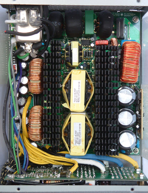
So far things have been pretty typical for a power supply review. After all, there are only so many ways to design a standard PSU chassis and provide cable harnesses. Now we come to the interesting part: the internals. Enermax did a tremendous job designing this power supply, but let's start at the beginning.
When I first saw the filtering stage, I asked the representatives at Enermax if CWT is the ODM. They responded by threatening to beat me up. ;-) Anyway, the filtering stage looks very good and has all of the necessary components. The coil sits on top of the PCB, covered with shrinking hose -- hence the similarity to CWT PSUs. Right nearby are the rectifier bridges, both without heatsinks. The PFC stage follows next and the coil is placed on a solid socket. Matsushita builds the three primary capacitors, rated for 220µF and 400V at 85°C.
Enermax is particularly proud of their transformers, since they synchronized both of them for quad forward circuitry. Two synchronized transformers will share the work equally, which makes the work more efficient. The power supply also features eight safety features such as OCP (Over Current Protection), UVP (Under Voltage Protection) for the AC part, UVP (Under Voltage Protection) for the DC part, OPP (Over Power Protection), OTP (Over Temperature Protection), SIP (Surge & Inrush Protection), and SCP (Short Circuit Protection).


This power supply uses a DC-to-DC topology, which means that the 3.3V and 5V rails do not come directly from the transformer anymore. The transformers can now be built for the sole purpose of delivering a stable 12V output. In DC-to-DC designs, so far the extra circuitry has been included on the main PCB in the secondary stage of the PSU. Enermax relocated this functionality to a sister PCB that we will describe in the next paragraph. The secondary stage in this power supply now only has to deal with the six 12V rails. The capacitors for this purpose are all made by Chemi-Con, one of the best but still affordable Japanese capacitor manufacturers.
So where are the 3.3V and 5V rails created? Let's have a look at the large sister PCB where the cable management sockets are located. The left side is where it happens. The upper part is for the 5V output and the bottom is for 3.3V. The output feeds directly into the cable harnesses, and from there on to the peripherals. Since this is done totally independent from the other 12V rails, this power supply can output 99% of its rated power on just the 12V rails, which we will verify in a moment. Other power supplies that generate the 5V and 3.3V rails from the transformer normally have problems with the voltage distribution if not loaded according to ATX-norm.


49 Comments
View All Comments
takumsawsherman - Thursday, November 6, 2008 - link
Forgive me for my ignorance, but isn't it the 5V rail that takes care of hard drive power? The reason I ask is that I have a Enermax Whisper 350 that is about 5 years old, and it has 32A on the 5V rail. I can use 4 Hard drives max before the power supply starts to have issues.Does this mean that this power supply could only handle 3? My 3.3 rail is also 30A, and this unit seems to only provide 25. Why so little?
Again, I am looking to be educated, I'm not yet criticizing because I realize that my assumptions are probably incorrect. I've been window shopping for Hard drives for a while now (750GB is not enough any more) and I know i can't add more to my current setup unless I get a better power supply.
Trippytiger - Friday, November 7, 2008 - link
I believe 3.5" hard drives receive power on both the +5V and +12V rails. That the power supplies for external hard drive enclosures provide both voltages suggests this.I'm guessing, given how old your PSU is and how much juice it has on the +5V and +3.3V rails, that its +12V rail is on the weak side and that's the reason it has issues with large numbers of hard drives. It sounds like it was designed to ATX 1.3 specs and was intended for system with a CPU running off of the 5V rail. Since all modern (and not so modern) processors take power from the +12V rail these days, the +5V rail just isn't as critical as it used to be.
You'd probably be much better off with a newer PSU with more power on the +12V rail. Of course, if your system does happen to be ancient... good luck finding something suitable. I went shopping for a PSU for my old AXP+ system several years ago and had a hell of a time finding a unit with a beefy +5V rail back then!
xaris106 - Thursday, November 6, 2008 - link
I`m not sure i understand that "syncronized transformers". But if they work in parallel I am a bit concerned for the approach as variations in the resistance, impendance and coupling factors between the two can lead to unbalanced loading. And it could get worse as components burn in and age.As for the kill a watt measurements I would like to point out that the number is not what the pc components need in power. It includes the psu loses. that means a 300W kill-a-watt measurement means the parts draw 240W (and the psu load) with a 80% efficient psu
JonnyDough - Thursday, November 6, 2008 - link
Try learning words like "kilowatt" and "losses" and then post.xaris106 - Thursday, November 6, 2008 - link
yeah I see why you said that... with "kill-a-watt" i was referring to the wattmeter device that people use in their electric outlets to measure power consumption. I wasn't referring to killowatts...I also misspelled "losses". again sorry for my english.The0ne - Friday, November 7, 2008 - link
You don't need to apologize for your grammar or misspellings on here. People need to understand that there are other members of different race and from different countries to not STUPIDLY assume that they are the only one that matters in the world. If the person is going to make such stupid comments lets see him/her try it on a non-english topic and then report back. Chances are, he/she is probably to lazy in the first place to pick up a second language to even consider trying.That aside, it's the web. Even I don't care about my grammar or spelling here and I write technical reports on a daily basis where I work (to a certain extent of course hahah).
JarredWalton - Friday, November 7, 2008 - link
The power loads in our PSU reviews are *not* measured using a Kill-A-Watt or similar device; see the page on the Chroma testing equipment. When we say there's a 500W load on a PSU and that PSU is 89% efficient at that load, it means the PSU is drawing 562W at the outlet. Our other articles use wall power (because we don't have the equipment elsewhere to measure actual loads).xaris106 - Friday, November 7, 2008 - link
Yes, I know you didn't use a simple wattmeter. Your equipment and test is impressive I would say. I was referring to a comment in page 1 that mentioned a kill-a-watt.As a suggestion, in reviews that you do use outlet power, it would be nice to make a note of it and that the numbers include power losses (and even the approximate efficiency if you use a tested psu) so people can have it in mind.
Now just an idea.Wouldn't it be nice for you to make a set of connectors that plug between the psu connectors and the motherboard/devices that can go through ampmeters? So we can see all those dc currents. Although that might me a lot of ampmeters...and a bit risky. Just a thought.
My regards.
The0ne - Friday, November 7, 2008 - link
I don't see why you can't hook up a current probe connected to a O-scope to measure the current.JarredWalton - Friday, November 7, 2008 - link
Christoph did something like that in his http://www.anandtech.com/casecoolingpsus/showdoc.a...">Power Supply Myths article... not really something to do in every review if we can avoid; they take long enough already! ;)