ASUS P5E3 Deluxe: X38 and DDR3 arrives... almost
by Gary Key on September 18, 2007 4:00 AM EST- Posted in
- Motherboards
ASUS P5E3 Deluxe: Board Layout and Features
ASUS has designed a board that reminds us of cars from yesteryear: large, solid, and seemingly engineered as if it's a tank ready for the front lines. The board easily installs into a variety of cases from Antec and Cooler Master. The majority of connections are easily reached within a full size ATX case. The board features an eight-phase voltage regulator system that contributes to the excellent stability we experienced throughout testing. The P5E3 Deluxe uses 100% Conductive Polymer Aluminum Solid Capacitors. ASUS installs a total of six fan headers (1 x 4-pin, 5 x 3-pin) which is an excellent decision in our opinion. The CPU and four of the five system fan headers can be controlled via the BIOS and the ASUS AI Suite program within Windows.
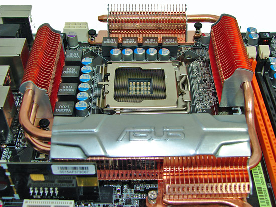
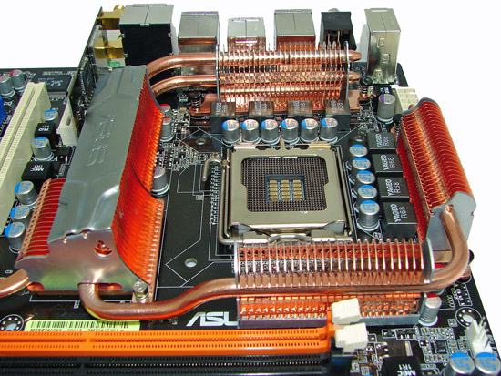
Around the CPU socket area, we find an ample amount of room for the majority of cooling solutions. We utilize the stock heatsink/fan in our base testing but also verify the ability to install several aftermarket socket 775 cooling solutions such as the Tuniq 120 and Thermalright Ultra-120 during our overclocking tests. The 8-pin EPS12V power connector is located on the edge of the board behind the PS/2 keyboard port and does not interfere with our various cooling units. However, based upon our preliminary overclocking tests, if a vertical mounted fan in an air cooling unit such as the Tuniq 120 or water cooling is utilized then additional cooling will be required on the MCH and PWM areas.
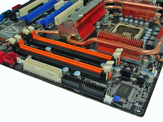
The DIMM module slots' color coordination is correct for dual channel setup based upon the premise of installing DIMMs in the same colored slots for dual-channel operation. The black and orange slot colors (Ed: Happy Halloween?) look out of place on this board, but then again we do not express any love for several board manufacturers who tend to use the entire Crayola color palette on their boards. Installing memory modules will be a slightly difficult affair with a full size video card placed in the first PCI-E x16 slot.
The 24-pin ATX power connector is properly located on the edge of the board along with the floppy drive connector. The CPU fan header is located on the far right edge of the board and works well with our test fans. Two additional fan headers are located on either side of the floppy and power connectors.
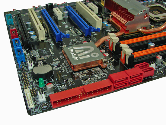
The positioning of the six red ICH9R SATA ports is excellent when utilizing the expansion slots. The ICH9R chipset is passively cooled and remained fairly cool to the touch throughout testing... well, at least until we installed our CrossFire setup and then it became quite toasty to the touch. The IDE connector is at a right angle next to the SATA ports and generally is easy to reach in our case. The chassis panel is located on the bottom left edge of the board along with the number three fan header. Right above those two items is a green LED power-on indicator, the battery, and the number four fan header. The two blue connectors are for the additional USB ports and the red connector is for the extra IEEE-1394 connector.
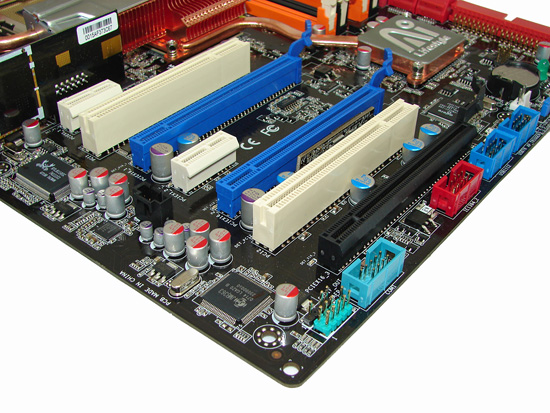
The board comes with three physical PCI-E x16 connectors (2 x16, 1 x8 electrical), two PCI-E x1 connectors, and two PCI 2.2 connectors. The second PCI-E x1 and PCI slots will be blocked by dual slot graphics cards. Several cards we tried in the first PCI-E x1 slot were a very tight fit if a full size card was used in the first PCI slot. Due to the location of the two x16 capable PCI-E slots, there is not much room for custom cooling solutions on the video cards. ASUS has informed us the Republic of Gamers board will have a different layout that will be conducive to custom cooling solutions. We also tried a TriFire setup on this board (three HD 2900 XT cards), but we did not have proper driver support for that to work at present - although we expect it soon.
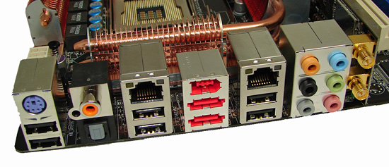
The rear panel contains the standard PS/2 keyboard port along with several other connectors. The panel also includes dual RJ-45 LAN ports with activity indicator lights, six USB ports, and optical/coaxial S/PDIF out ports. The audio panel consists of six ports that can be configured for 2, 4, 6, and 8-channel audio connections for the ADI 1988B HD codec. The board contains an 802.11n specification WiFi card that worked flawlessly with several different Draft N routers. Finally, there are two eSATA ports along with an IEEE-1394 port which completes a back panel that pretty much covers a wide array of options designed with the home user in mind.
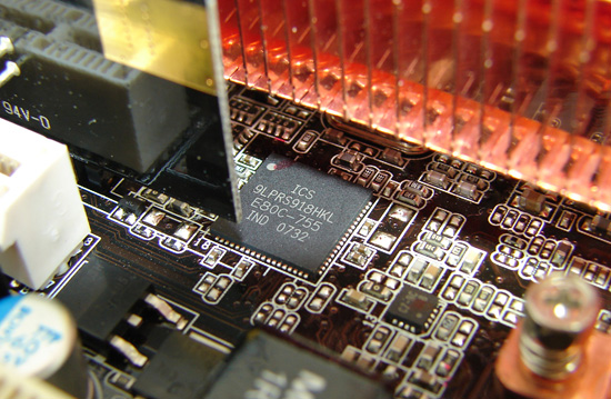
ASUS will utilize the ICS 9LPRS918HKL clock control chipset on this board.
 |
| Click to enlarge |
ASUS has designed a board that reminds us of cars from yesteryear: large, solid, and seemingly engineered as if it's a tank ready for the front lines. The board easily installs into a variety of cases from Antec and Cooler Master. The majority of connections are easily reached within a full size ATX case. The board features an eight-phase voltage regulator system that contributes to the excellent stability we experienced throughout testing. The P5E3 Deluxe uses 100% Conductive Polymer Aluminum Solid Capacitors. ASUS installs a total of six fan headers (1 x 4-pin, 5 x 3-pin) which is an excellent decision in our opinion. The CPU and four of the five system fan headers can be controlled via the BIOS and the ASUS AI Suite program within Windows.
Around the CPU socket area, we find an ample amount of room for the majority of cooling solutions. We utilize the stock heatsink/fan in our base testing but also verify the ability to install several aftermarket socket 775 cooling solutions such as the Tuniq 120 and Thermalright Ultra-120 during our overclocking tests. The 8-pin EPS12V power connector is located on the edge of the board behind the PS/2 keyboard port and does not interfere with our various cooling units. However, based upon our preliminary overclocking tests, if a vertical mounted fan in an air cooling unit such as the Tuniq 120 or water cooling is utilized then additional cooling will be required on the MCH and PWM areas.
The DIMM module slots' color coordination is correct for dual channel setup based upon the premise of installing DIMMs in the same colored slots for dual-channel operation. The black and orange slot colors (Ed: Happy Halloween?) look out of place on this board, but then again we do not express any love for several board manufacturers who tend to use the entire Crayola color palette on their boards. Installing memory modules will be a slightly difficult affair with a full size video card placed in the first PCI-E x16 slot.
The 24-pin ATX power connector is properly located on the edge of the board along with the floppy drive connector. The CPU fan header is located on the far right edge of the board and works well with our test fans. Two additional fan headers are located on either side of the floppy and power connectors.
The positioning of the six red ICH9R SATA ports is excellent when utilizing the expansion slots. The ICH9R chipset is passively cooled and remained fairly cool to the touch throughout testing... well, at least until we installed our CrossFire setup and then it became quite toasty to the touch. The IDE connector is at a right angle next to the SATA ports and generally is easy to reach in our case. The chassis panel is located on the bottom left edge of the board along with the number three fan header. Right above those two items is a green LED power-on indicator, the battery, and the number four fan header. The two blue connectors are for the additional USB ports and the red connector is for the extra IEEE-1394 connector.
The board comes with three physical PCI-E x16 connectors (2 x16, 1 x8 electrical), two PCI-E x1 connectors, and two PCI 2.2 connectors. The second PCI-E x1 and PCI slots will be blocked by dual slot graphics cards. Several cards we tried in the first PCI-E x1 slot were a very tight fit if a full size card was used in the first PCI slot. Due to the location of the two x16 capable PCI-E slots, there is not much room for custom cooling solutions on the video cards. ASUS has informed us the Republic of Gamers board will have a different layout that will be conducive to custom cooling solutions. We also tried a TriFire setup on this board (three HD 2900 XT cards), but we did not have proper driver support for that to work at present - although we expect it soon.
The rear panel contains the standard PS/2 keyboard port along with several other connectors. The panel also includes dual RJ-45 LAN ports with activity indicator lights, six USB ports, and optical/coaxial S/PDIF out ports. The audio panel consists of six ports that can be configured for 2, 4, 6, and 8-channel audio connections for the ADI 1988B HD codec. The board contains an 802.11n specification WiFi card that worked flawlessly with several different Draft N routers. Finally, there are two eSATA ports along with an IEEE-1394 port which completes a back panel that pretty much covers a wide array of options designed with the home user in mind.
ASUS will utilize the ICS 9LPRS918HKL clock control chipset on this board.


60 Comments
View All Comments
strikeback03 - Thursday, September 20, 2007 - link
My question about the heatpipe cooling is related to this:So why are these companies creating cooling solutions that work best with inferior CPU cooling? The heatpipe towers and water certainly seem to be the best CPU cooling, but the board cooling system looks like it was designed to work with the stock Intel cooler.
mostlyprudent - Tuesday, September 18, 2007 - link
I couldn't be happier to see the passive heatpipe cooling. After reading the reports of the X38 being a "hot" chipset, I was worried that I would be back to screaming/failing little chipset fans...whew...thank goodness.n0nsense - Tuesday, September 18, 2007 - link
there always water cooling option. which i'm thinking about.One circuit for CPU, GPU, NB and SB (like Nautilus 500) + Termalright for mofsets should be perfect for sane overclocking and quiet PC.
Etern205 - Tuesday, September 18, 2007 - link
I guess what they mean by "upside down" is do not install into aBTX case?
n0nsense - Tuesday, September 18, 2007 - link
No, they meant that the only (the best) way to install this boards is when CPU socket located on the upper side.look at the picture of CS-718. in this case CPU socket is in the lowest part. This mean that hotest part of heatpipe system is higher then coolest. Heatpipe working the best when coolant vaporized at hotest part, then liquefied at coolest (radiators). Liquefied coolant should return somehow to the hotest part (chipset), and when motherboard "normally" this done by gravity. When the board installed in "upside-down" or horizontally, this SHOULD be done by capillaries, which are way less effective according to Asus support and wiki.
Etern205 - Tuesday, September 18, 2007 - link
I was right about this "do not install into a BTX case"The Enermax CS-718 supports ATX motherboards, but the design is based on the BTX specs.
On a correct ATX case, if the back of the case if facing you, then you will open the panel on the right. And when the opening is facing you the front will face to the right.
http://img221.imageshack.us/img221/2901/1015uh6.jp...">Image
As for BTX if it's place into the same position, then you will open the panel on the left, which is what the Enermax CS-718 is designed to be and when the opening is facing you the front will face to the left. http://img175.imageshack.us/img175/6379/1007xq2.jp...">Image
JarredWalton - Tuesday, September 18, 2007 - link
FYI, I deleted your (numerous) multiple posts. A little bit of patience goes a long way. Once or twice I can understand, but three sets of multiple posts? Hopefully that was just a weird error on the part of your system.n0nsense - Wednesday, September 19, 2007 - link
it is a problem with my computer @ work.I guess it's caused by Synergy.
Anyway, thank you for clearing my extra messages. It's sad that i can't remove or edit my own messages.
n0nsense - Wednesday, September 19, 2007 - link
it is a problem with my computer @ work.I guess it's caused by Synergy.
Anyway, thank you for clearing my extra messages. It's sad that i can't remove or edit my own messages.
8steve8 - Tuesday, September 18, 2007 - link
is the intel g35 chipset launching with the x38? if not, when will it launch?while the x38 doesnt offer much tangable to the users of p35 or 965p, especially those of us that are sane (ddr2 users), the g35 appears to offer a vastly improved 3d engine, and native hdmi support. "vastly improved" over the g965 and g33, which, for example, i can play warcraft3 at 1600x1200 w/full settings... this is onboard video... very impressive.