The Single 12V Rail SilverStone Olympia OP650
by Christoph Katzer on July 13, 2007 12:00 PM EST- Posted in
- Cases/Cooling/PSUs
Secondary Side
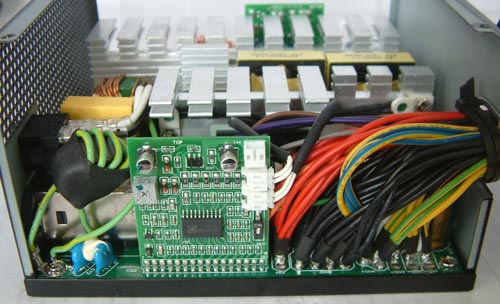
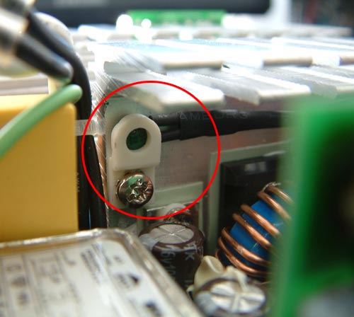
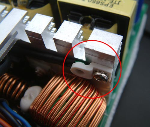
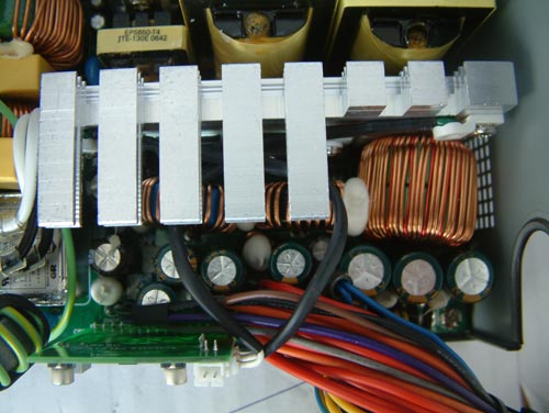
The secondary side has its own printed circuit board just as the primary side does. The board contains the protection features (including OCP, OPP, SCP, and UVP) and the fan control. The fan control is connected to two temperature sensing diodes which have been attached to the secondary heatsink (the hotter heatsink while running). They are attached on the right and left side and interact with each other to control the speed of the fan. The upper connector on the PCB is the output to the fan on the upper side of the power supply. The output is controlled through a potentiometer.
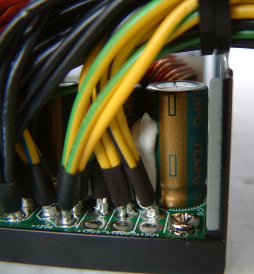
On the lower right edge of the PCB we found a small switch. This switch is actually to turn off the OCP on each of the four 12v rails to "combine" them into a single one. This is a very common method as most other manufacturers approach rail separation the exact same way. Normally separated 12v rails can be generated with just these separated OCPs on each rail. They have one or two 12v rails and just split them into a few more in order to show a higher number of 12v rails.
All the capacitors on the secondary side are from Taepo. The company is quite popular and used by many other manufacturers as well. The cables are nicely connected to the PCB and all of the cables have shrinking hoses in the end, how it should to be for certain security matters. The coils have a very good winding quality like all the others in this PSU as well. It would have been nice if Silverstone had started the sleeves of the cables inside of the PSU. This raises the overall quality and importantly for most users it looks better.
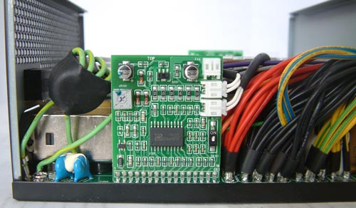
The secondary side has its own printed circuit board just as the primary side does. The board contains the protection features (including OCP, OPP, SCP, and UVP) and the fan control. The fan control is connected to two temperature sensing diodes which have been attached to the secondary heatsink (the hotter heatsink while running). They are attached on the right and left side and interact with each other to control the speed of the fan. The upper connector on the PCB is the output to the fan on the upper side of the power supply. The output is controlled through a potentiometer.
On the lower right edge of the PCB we found a small switch. This switch is actually to turn off the OCP on each of the four 12v rails to "combine" them into a single one. This is a very common method as most other manufacturers approach rail separation the exact same way. Normally separated 12v rails can be generated with just these separated OCPs on each rail. They have one or two 12v rails and just split them into a few more in order to show a higher number of 12v rails.
All the capacitors on the secondary side are from Taepo. The company is quite popular and used by many other manufacturers as well. The cables are nicely connected to the PCB and all of the cables have shrinking hoses in the end, how it should to be for certain security matters. The coils have a very good winding quality like all the others in this PSU as well. It would have been nice if Silverstone had started the sleeves of the cables inside of the PSU. This raises the overall quality and importantly for most users it looks better.


46 Comments
View All Comments
mindless1 - Wednesday, July 18, 2007 - link
Teapo are not considered the "best" alternative in electrolytics but through several years of use PSU owners have found their performance generally acceptible. They are not one of the typically problematic caps seen to fail frequently in PSU.It is just unfounded to think they're not 105C caps, odds are very high that they are on the secondary side as practically all very-low ESR caps these days are 105C rated. While the large primary caps aren't always 105C, often 85C, it is seldom we ever see them fail because there is a much lower ripple current ratio on the high (voltage) side, ESR vs physical size means there's very little self heating.
Also, a heatsink is meant to be a higher thermal density having the purpose of spreading out heat conducted from the (diodes, etc) parts on secondary side. Conduction of this heat through air to adjacent parts is low and the caps won't be heated as much as you seem to suspect merely by having the heatsink at 90 degrees.
However, it does not change your point about higher heat levels in the PSU ultimately leading to a shorter life. We would need more measurements of the capacitor tops (and mathematically solve for cap core temp) to arrive at some kind of end of life projection, but even then end of life is considered to be falling below cap manufacturers specs, which in a well engineered PSU with a lot of margin could still mean that even if the cap is below IT'S spec, it is still functionally acceptible for use in the PSU without it falling outside of acceptible ATX spec ranges.
Yes better caps would be nice, yes lowering temps would be good too. Unfortunately too many people act as though a 600W+ PSU is supposed to be quiet when even at today's 80% efficiency target that would mean 150W of heat that must be removed.
kilkennycat - Friday, July 13, 2007 - link
I have personally witnessed a UL-certified fibreglass circuit board catch fire due to an inner-layer power-plane to ground short at a feed-through hole, initially stimulated by physical damage to the board by a component overheating and over-currenting the feed-through causing it to burn-out and generate a low-impedance path between the adjacent inner-layer power-planes with a ring of carbonized circuit-board material. (In modern circuit boards, signal feedthroughs often pass through close-tolerance clearance-holes on inner-layer power-planes ) Due to the conduction of the carbon across the edges of the inner-layer planes, the board will actually burn - fire-retardant or not - generating a larger and larger carbon-edged hole, until one of the following happens:-* The power source is removed and the board instantly self-extinguishes.
* the current density around the hole as it enlarges becomes reduced sufficiently to allow the self-extinguishing property of the UL-certified fibreglass to gain the upper hand.
Unfortunately the carbonized edge of the hole is not a short-circuit and thus the current-limit of the power-supply is likely to be the only limiting protection. So, if 54 amps just happens to be available instead of 20amps, there is a strong possibility that a burning circuit board can damage a bunch of other components and cause a secondary fire before the hole is big enough for the current density to fall low enough for the board to finally self-extinguish.
Intel's per-line current limit recommendation is built on very good safety/reliability science. Buy one of these power-supplies and disable the individual-line current limits at your own risk.
mindless1 - Wednesday, July 18, 2007 - link
While your comment is interesting, it's non-applicable here because these are only one layer per side boards (if that, many PSU still use pretty poor paperboard and single-sided PCB).Intel's recommendation is based on amps/rail leaving the PSU casing, it does not stipulate nor limit what the current capability would be between a power and ground plane (if such a board design existed, but none do AFAIK (on a high current PC PSU, I don't rule out such a design in a notebook or other CE devices) as mentioned above.
Vidmar - Friday, July 13, 2007 - link
While I think the Efficiency charts in load percentage are nice, if you included Efficiency charts in watts it would be more informative from a buying perspective.The reason? I know the sum of system load is 375watts normally. The way it is now, if power supply XYZ has a max load of 650watts, I have to calculate where my ~375watts falls into that load chart (~57% load). But if the next power supply has 1000 watts max, then I have to yet again calculate what load percentage that may be for *that* power supply. If the Efficiency charts were in watts, instead of load, no calculations would be necessary. If I could look at your charts and see that XYZ power supply provided those watts the most efficiently, that would be the power supply I would get.
Maybe you could just provide a second X axis on the chart that included the watts.
Thanks!
Souka - Friday, July 13, 2007 - link
I picked up one of these OP650 units. Worked well in my system, but emitted a buzzing/chirping noise with any graphic change 2D and 3D.I was in immediate need for a presentation so bought my friends Corsair 620HX...which met my needs.
The Corsair is queiter at idle and load in my system, and has modular cabling as better power effeciencicy if I remember right.
Kudos to Silverstone for good tech support and willing-ness to replace my unit....I ended up returning to the on-line place and they paid for all shipping charges and no fees. Silverstone said if I had any problems such as restocking fees or shipping fees they'd help out.
Good job Silverstone...stand behind your products! I will likely buy from them next time I need a PS
Christoph Katzer - Friday, July 13, 2007 - link
Thank you all for the feedback again. I think I can answer most of you with saying that we already work on the additonal tests. Some additional tests do need more time but will follow. PCP&C Silencer will follow next and it's well worth waiting for it.Belldandy - Friday, July 13, 2007 - link
Sounds like a nicely built power supply that has problems with voltage drops. I've had a few hard drives fail because of voltage drop in the 5V rails. The 4 rail design puts the graphics cards on rail4, so does that mean if you run a 8800GTS/GTX SLI setup, it will overload the 4th rail when power is available on rail 3? I would like to see a test of the PC P&C 750W Silencer Quad, which claims to be a single rail 60A design. I'm considering getting the silencer unit to replace my OCZ GameXtreme 600W which suffers ripple voltage problems.saratoga - Friday, July 13, 2007 - link
Intel considers more then 20 amps in a rail to be a fire hazard. If you short a 12v rail to a grounded case, you can pump more amps into your ground line then your house's wiring can handle, but since your circuit breaker isn't on the ground line, you'll never trip the breaker. In that case the only thing between you and burning your house down is the limiter on the power supply, hence the 20 amp requirement.
I don't know how big of a risk this is in practice, but thats the official explanation.
qpwoei - Saturday, July 14, 2007 - link
Not if the power supply is constructed correctly. ATX power supplies are required to be SELV systems, which means that crowbaring and output to an external ground will simply result in a shift of the internal ground level and no current will flow. This is actually done for electrocution safety reasons - even if ATX PSUs had 500V outputs, you'd still be pretty much safe from electrocution.
Additionally, the restriction is in power, not current. It's 240 VA limited, so 12 V at 20 A, or 5 V at 48 A, or 3.3 V at 73 A.
The real reason for the restriction is to limit the danger if an output gets tied to an internal ground. The resulting power being dissipated in a screwdriver (for example) can result in bits of the screwdriver getting turned into plasma, blasting bits of hot metal everywhere. Even if you don't get such an explosive response, you still have a fire danger (inside the case, not in your house).
LTG - Friday, July 13, 2007 - link
This is exactly what what is missing from the first page of the article.I think the author said Intel wanted it for "security" reasons when he meant "safety" reasons which made it hard to infer the fire issue.
Or maybe it is security and 4 rails makes it harder to hack into your system.