FSB Overclocking Results
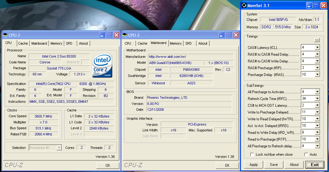
We were able to reach a final benchmark stable setting of 7x515 FSB resulting in a clock speed of 3605MHz. The board was capable of running up to 7x525 FSB but would consistently fail our Dual Prime95 test, although it passed all our game and synthetic benchmarks. We settled on the 7x515 FSB setting and set our VCore to an acceptable 1.4850V with Vdroop being around .02V during load testing. We were able to operate our GEIL memory at 4-4-4-12 at 2.4V with these settings.
The BIOS allows you to manipulate the MCH strap and memory speeds resulting in a wide variety of performance options based on your components. The current BIOS allows you to stay in the 1067 strap up to the 525FSB ceiling with our E6300 and E6400 chips, and this allows for some incredible memory and system performance at the higher FSB settings. Our E6600 has hit 7x550FSB in initial testing at this time. Our board was extremely stable throughout testing although we noticed the requirement for slightly higher memory voltages at the upper FSB rates due to the tight sub-timings. During overclocking we generally found that at 7x400 and above with our E6300 and the memory set at a 1:1 ratio (800 DDR2) that 4-4-4 timings were up to 7% faster in our benchmarks than forcing the memory latencies to 3-3-3 as the sub-timings were set tighter resulting in improved throughput.
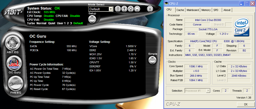
One minor issue we noticed with µGuru is that any setting over the 525FSB limit at this time would still result in the board be able to POST and boot into XP while generating FSB and clock rates that were not real. In our example we set the board to 6x555FSB. It would POST and display 6x555 along with the corresponding memory speed, and once in Windows the µGuru utility would show the same BIOS settings and allow changes to it. However, the system actually would default to the base 266FSB speed with memory at the base settings also.
Memory Stress Testing
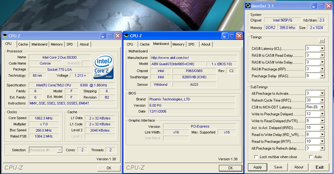
We take a look now at seeing how well our GEIL PC2-6400 memory operates in this board in both two and four DIMM testing. The screenshot above shows the actual memory settings used in our benchmark tests of the board. We do not modify the memory timings beyond the four major settings in our charts. The balance of memory settings are implemented automatically via the BIOS. abit implements slightly tighter memory and MCH timings than some of the other P965 boards we have tested.
We were able to set our timings to 3-3-3-9 by increasing the memory voltage to 2.20V with our GEIL memory. We were able to hold these timings up to DDR2-880 on this board before switching over to timings of 4-4-4-12 up to DDR2-1030 at 1:1 timings. We then switched to 5-5-5-15 timings at a 7x465 with a 4:5 ratio that resulted in a maximum stable memory speed of DDR2-1163. We tried out our Corsair Dominator PC-8888 and OCZ Flex XT memory but could not get the board stable at memory speeds greater than DDR2-1163.
Our settings of 3-4-4-12 at 2.275V were not quite as good as our ASUS P5B-E 1.02G settings of 3-4-3-10, but due to fairly tight memory timings elsewhere the benchmark results were actually better. We were able to keep this setting up to DDR2-860 before switching over to 4-4-4-12 settings that held stable until we reached DDR2-960 during our overclocking tests. The board was able to handle settings of 5-4-4-12 up to DDR2-1010. Our final settings of 5-5-4-15 at DDR2-1030 required a voltage increase to 2.325V.
| abit AB9 QuadGT Overclocking Testbed |
|
| Processor: | Intel Core 2 Duo E6300 Dual Core, 1.86GHz, 2MB Unified Cache 1066FSB, 7x Multiplier |
| CPU Voltage: | 1.4850V (default 1.3250V) |
| Cooling: | Tuniq Tower 120 |
| Power Supply: | OCZ GameXStream 700W |
| Memory: | GeIL PC2-6400 800MHz Plus (2x1GB - GX22GB6400PDC) (Micron Memory Chips) |
| Video Cards: | 1 x MSI X1950XTX |
| Hard Drive: | Seagate 320GB 7200RPM SATA2 16MB Buffer |
| Optical Drive: | Sony 18X AW-Q170A-B2 |
| Case: | Cooler Master CM Stacker 830 |
| Maximum CPU OC: | 515x7 (4-4-4-12, 1:1, 2.400V), CPU 1.4850V 3605MHz (+93%) |
| . | |
 |
| Click to enlarge |
We were able to reach a final benchmark stable setting of 7x515 FSB resulting in a clock speed of 3605MHz. The board was capable of running up to 7x525 FSB but would consistently fail our Dual Prime95 test, although it passed all our game and synthetic benchmarks. We settled on the 7x515 FSB setting and set our VCore to an acceptable 1.4850V with Vdroop being around .02V during load testing. We were able to operate our GEIL memory at 4-4-4-12 at 2.4V with these settings.
The BIOS allows you to manipulate the MCH strap and memory speeds resulting in a wide variety of performance options based on your components. The current BIOS allows you to stay in the 1067 strap up to the 525FSB ceiling with our E6300 and E6400 chips, and this allows for some incredible memory and system performance at the higher FSB settings. Our E6600 has hit 7x550FSB in initial testing at this time. Our board was extremely stable throughout testing although we noticed the requirement for slightly higher memory voltages at the upper FSB rates due to the tight sub-timings. During overclocking we generally found that at 7x400 and above with our E6300 and the memory set at a 1:1 ratio (800 DDR2) that 4-4-4 timings were up to 7% faster in our benchmarks than forcing the memory latencies to 3-3-3 as the sub-timings were set tighter resulting in improved throughput.
 |
| Click to enlarge |
One minor issue we noticed with µGuru is that any setting over the 525FSB limit at this time would still result in the board be able to POST and boot into XP while generating FSB and clock rates that were not real. In our example we set the board to 6x555FSB. It would POST and display 6x555 along with the corresponding memory speed, and once in Windows the µGuru utility would show the same BIOS settings and allow changes to it. However, the system actually would default to the base 266FSB speed with memory at the base settings also.
Memory Stress Testing
 |
| Click to enlarge |
We take a look now at seeing how well our GEIL PC2-6400 memory operates in this board in both two and four DIMM testing. The screenshot above shows the actual memory settings used in our benchmark tests of the board. We do not modify the memory timings beyond the four major settings in our charts. The balance of memory settings are implemented automatically via the BIOS. abit implements slightly tighter memory and MCH timings than some of the other P965 boards we have tested.
| abit AB9 QuadGT Stable DDR2-800 Timings - 2 DIMMs (2/4 slots populated - 1 Dual-Channel Bank) |
|
| Clock Speed: | 800MHz |
| CAS Latency: | 3 |
| RAS to CAS Delay: | 3 |
| RAS Precharge: | 3 |
| RAS Cycle Time: | 9 |
| Voltage: | 2.20V |
We were able to set our timings to 3-3-3-9 by increasing the memory voltage to 2.20V with our GEIL memory. We were able to hold these timings up to DDR2-880 on this board before switching over to timings of 4-4-4-12 up to DDR2-1030 at 1:1 timings. We then switched to 5-5-5-15 timings at a 7x465 with a 4:5 ratio that resulted in a maximum stable memory speed of DDR2-1163. We tried out our Corsair Dominator PC-8888 and OCZ Flex XT memory but could not get the board stable at memory speeds greater than DDR2-1163.
| abit AB9 QuadGT Stable DDR2-800 Timings - 4 DIMMs (4/4 slots populated - 2 Dual-Channel Bank) |
|
| Clock Speed: | 800MHz |
| CAS Latency: | 3 |
| RAS to CAS Delay: | 4 |
| RAS Precharge: | 4 |
| RAS Cycle Time: | 12 |
| Voltage: | 2.275V |
Our settings of 3-4-4-12 at 2.275V were not quite as good as our ASUS P5B-E 1.02G settings of 3-4-3-10, but due to fairly tight memory timings elsewhere the benchmark results were actually better. We were able to keep this setting up to DDR2-860 before switching over to 4-4-4-12 settings that held stable until we reached DDR2-960 during our overclocking tests. The board was able to handle settings of 5-4-4-12 up to DDR2-1010. Our final settings of 5-5-4-15 at DDR2-1030 required a voltage increase to 2.325V.


41 Comments
View All Comments
yyrkoon - Monday, January 22, 2007 - link
Oh, Gary, and Jarred, if you're thinking we, your readers are being harsh on you, well perhaps we are to an extent, but speaking for myself, this is because we care, and often look forward to your articles. So think of this as constructive criticism, and not outright flaming, please.Gary Key - Tuesday, January 23, 2007 - link
You are not being harsh. I changed the article back to "Conductive Polymer Aluminum Solid Capacitors" as abit finally confirmed the majority of the capacitors on the board are this type (I looked up the capacitor part numbers before hand but edited the article back the other way). I will update it when they confirm the three capacitors that did not match, they are solid but I have two boards each with different part numbers/suppliers on those three items. At times the manufacturers want us to use their marketing terminology as they might change components during production lot runs based on engineering changes or spot market pricing or to use layman's terms on the website. My previous articles on the Gigabyte boards used the correct terminology based on the capacitors on the board and we had an enormous amount of email and forum traffic asking why we stated something different than on Gigabyte's website at the time. We dumbed it down a little this time after a discussion and should not have. ;) Thanks for the comments and we do listen.yyrkoon - Monday, January 22, 2007 - link
Like the man said, Solid State is used when referring to Integrated Circuits, not Capacitors. The end result, is that you end up 'looking' like a fool, when someone who knows better sees this ( and possibly spread a minor form if 'mis-information).Think about it like this, what is the difference between a NAS, and a SAN ? Would you call a SAN, a NAS, in the company of enterprise IT geeks ? Probably not, at least, not without causing some confusion, or being corrected several times in the process . . .
Operandi - Monday, January 22, 2007 - link
Well they (caps suitable for motherbards) are either AL electrolyte or solid polymer based.Electrolyte caps are the more common type an actually contain electrolytic fluid which can leak when the cap fails. Polymer caps avoid that problem and also last longer -- to the laymen that would be the key difference.
Gary Key - Monday, January 22, 2007 - link
I have used the terminology, "Conductive Polymer Aluminum Solid Capacitors" in past articles and received several emails asking why we do not use what the manufacturers state on their websites as that term was deemed confusing. :)Stele - Monday, January 22, 2007 - link
Part of the problem lies in the confusion about the various kinds of capacitors of that category.Amongst the kind that we're concerned with on motherboards, graphics cards etc, we have the most basic: the aluminium electrolytic capacitor. Because this type started out with liquid electrolyte, the word "liquid" is generally omitted from the name as it is understood.
Then came the solid aluminium electrolytic capacitor, which replaced the liquid electrolyte with, well, a solid one - usually based on aluminium oxide. These are the type that we're nowadays excited about - the lack of liquid makes them more resistant to blow-outs and electrolyte leakage/dry-out, especially under prolonged, high temperature use. For short, they're sometimes referred to as merely "solid electrolytic" ("aluminium" is sometimes left out because, as noted above, the solid electrolyte is usually based on aluminium oxide and hence is understood as such) capacitors. To call them "solid capacitors" isn't totally useful because most capacitors are indeed solid objects :)
In conductive polymer capacitors, on the other hand, the dielectric is made from polymer foil (e.g. polypropylene, polyester, polystyrene, polycarbonate) coated with a layer of metal deposited on the surface. It follows that the basic conductive polymer capacitor has no liquid electrolyte inside - indeed there is no electroylte as the dielectric is purely the polymer foil.
However, manufacturers can and do mix in aluminium electrolyte with the polymer foil to improve certain performance characteristics; the electrolyte is often solid (rather than liquid) aluminium-based, hence "conductive polymer aluminium solid electrolytic capacitor".
As such, the exact names can mean quite distinct types of capacitors, and are not merely loose permutations of words like "electrolytic", "aluminium", "solid" and "polymer"... so if one wants to accurately describe a capacitor being used, one would need to double-check exactly what dielectric is being used in that capacitor :)
Marlin1975 - Monday, January 22, 2007 - link
Thats a understatement. The only thing i don't like about my 965 board is lack of IDE and the use of the jmicron junk.
One of the reasons I am waiting for more 650i boards and the ?last? ati chipset for Intel chips.
LoneWolf15 - Monday, January 22, 2007 - link
It's one of the reasons I'd still chose i975x rather than i965 for a chipset. i975X still has native Intel IDE.Due to recent nVidia chipset/board issues, and past issues with heat production, I'm not sure I'd choose them for an Intel board either, so that leaves the i975X as the only chipset I'd be comfortable with.
Numb3rs - Thursday, January 25, 2007 - link
Honestly, what in a new build would require and IDE interface..? eSATA is important and I am glad it's included. Abit has always made mobos dropping legacy devices no longer used by enthusiasts. Look at their old Abit "MAX" boards.
Why, in 2007 are manufacturers still using serial and parrallel I/O's..? Remove them completly and free the backplane for more useful eSATA, USB..etc
LoneWolf15 - Friday, January 26, 2007 - link
Obviously, you've never configured a Cisco router through its console port (which usually requires a serial port). And perhaps I don't want my list of optical drives confined to only SATA (currently Plextor and LiteOn are my only options, and I don't want one due to price and the other due to writing quality reasons).There are also some known issues with using Symantec Ghost on the JMicron chipset. Unless I hear they are worked out, that's an important thing to me too, and so IDE is still important to me. Just because it isn't useful to you doesn't mean it isn't to a lot of others.