Abit AB9 Pro: A sneak peek at Intel's new P965 chipset
by Gary Key on July 3, 2006 3:45 AM EST- Posted in
- Motherboards
Board Layout and Features
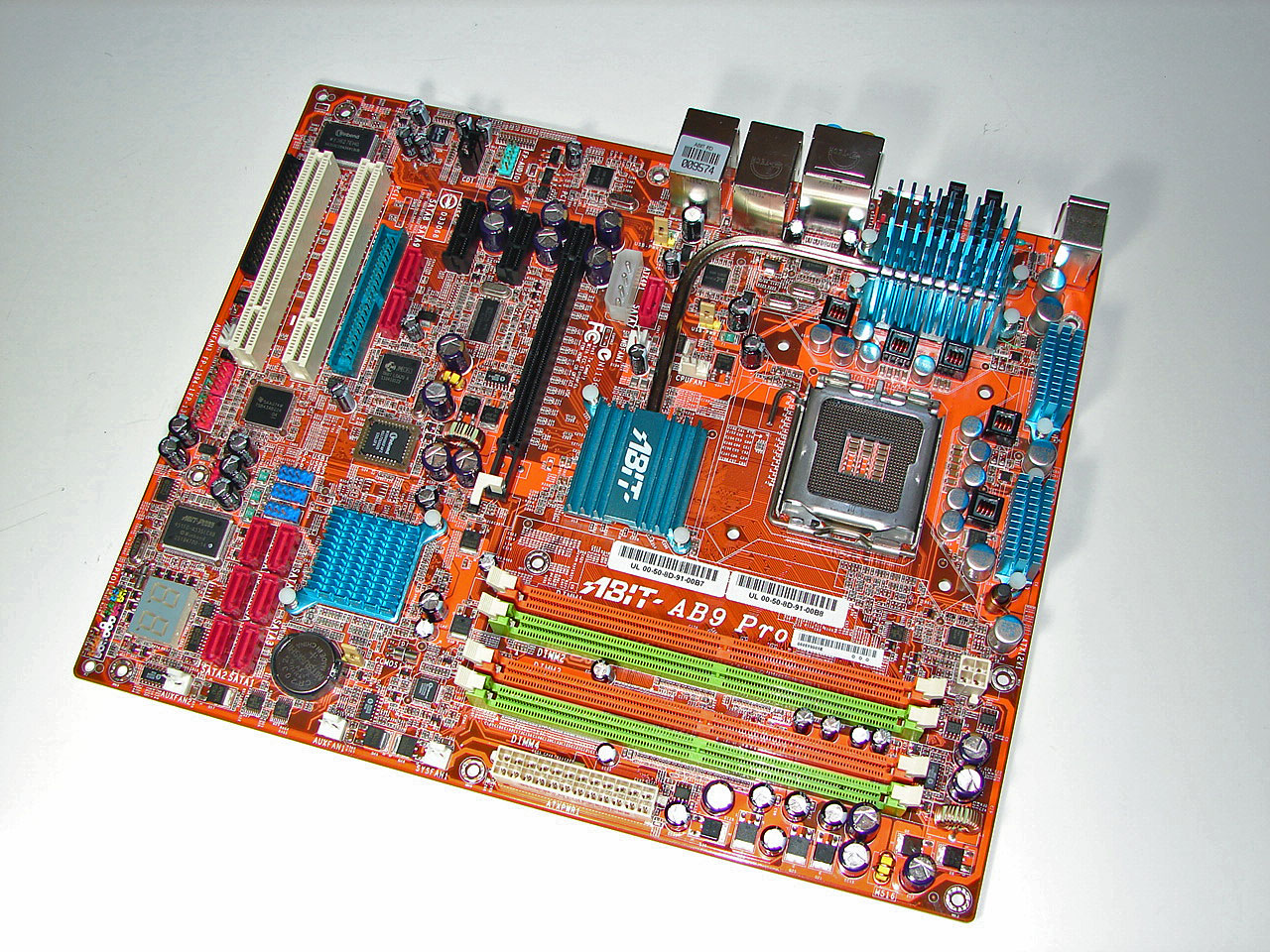
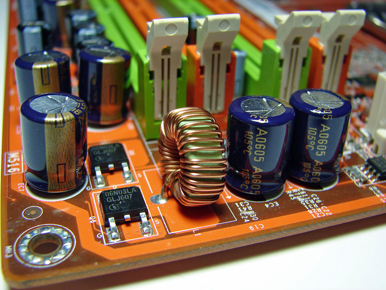
Abit designed a board that has one of the more interesting layouts we have seen in our labs in a long time. While the board was very easy to install in our mid-size ATX case, we did have some issues with utilizing our optical drive in the top bay due to the location of the JMicron powered IDE port that is located in between the number two PCI Express X1 slot and the number one PCI slot. The Abit board features an excellent voltage regulator power design with high quality capacitors located in each major component section of the board that yielded superb stability with our early BIOS revisions. Our board was able to POST our 805D at 4660MHz but we could not enter Windows due to the inability to change memory timings with the current BIOS. We certainly foresee this board being excellent at overclocking if the BIOS matures properly.
The DIMM module slots' color coordination is correct for dual channel setup based upon the premise of utilizing different colors for each memory bank. The memory modules are easy to install with a full size video card placed in the first PCI Express X16 slot. The 24-pin ATX power connector is located along the edge of the board along with a series of capacitors for the memory modules. Abit places the four-pin 12v auxiliary power connector at the top of the first memory module but completely out of the way of aftermarket cooling solutions.
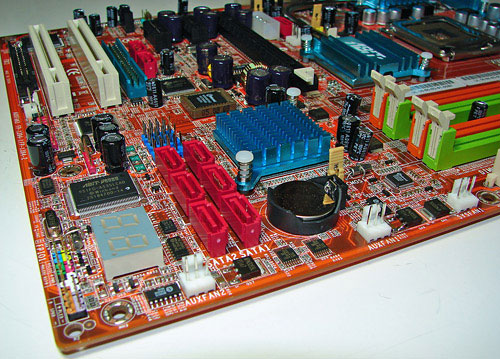
The six Intel ICH8R SATA ports are color coded red and are located to the left of the ICH8R Southbridge and battery. The SATA ports feature the newer clamp and latch design. We found the positioning of the SATA ports to be excellent when utilizing either the PCI-E X1 or PCI 2.3 slots. The ICH8R is passively cooled and remained cool to the touch throughout testing.
The first three of five auxiliary fan connectors are located at the bottom edge of the board. The clear CMOS jumper is color coded yellow and is located in between the battery and ICH8R chipset. The CP80P POST port debug LED, chassis panel, µGuru chipset, and red 1394a connectors are located along the left edge of the board. The blue USB 2.0 connectors are located above the SATA ports.

The board comes with one physical PCI Express X16 connector, two PCI Express X1 connectors, and two PCI 2.3 connectors. The layout of this design offers a very good balance of expansion slots for a mainstream board while providing excellent clearance space for graphics card utilization. However, the layout in this area is very unusual if not a bit chaotic. Our main issue is the location of the floppy drive connector at the bottom of the board along with the JMicron JMB363 IDE and SATA ports being sandwiched in between the PCI-E and PCI slots in the middle of the board.
The four-pin molex power connector that will be required for future GPU products and the Silicon Image 3132 SATA port is located above the PCI-E X16 slot. The P965 chipset will not officially support CrossFire or SLI operation so the lack of a secondary PCI-E X16 slot means this board could have been arranged differently. However, Abit informed us that some of the unusual port locations were predicated upon ensuring proper power delivery, stability, and trace layouts based upon the capacitor locations. That may be true, but we think they would do better to add more capacitors and do whatever else is necessary to accommodate a more ideal layout, as frankly the current layout really isn't what we'd like to see.
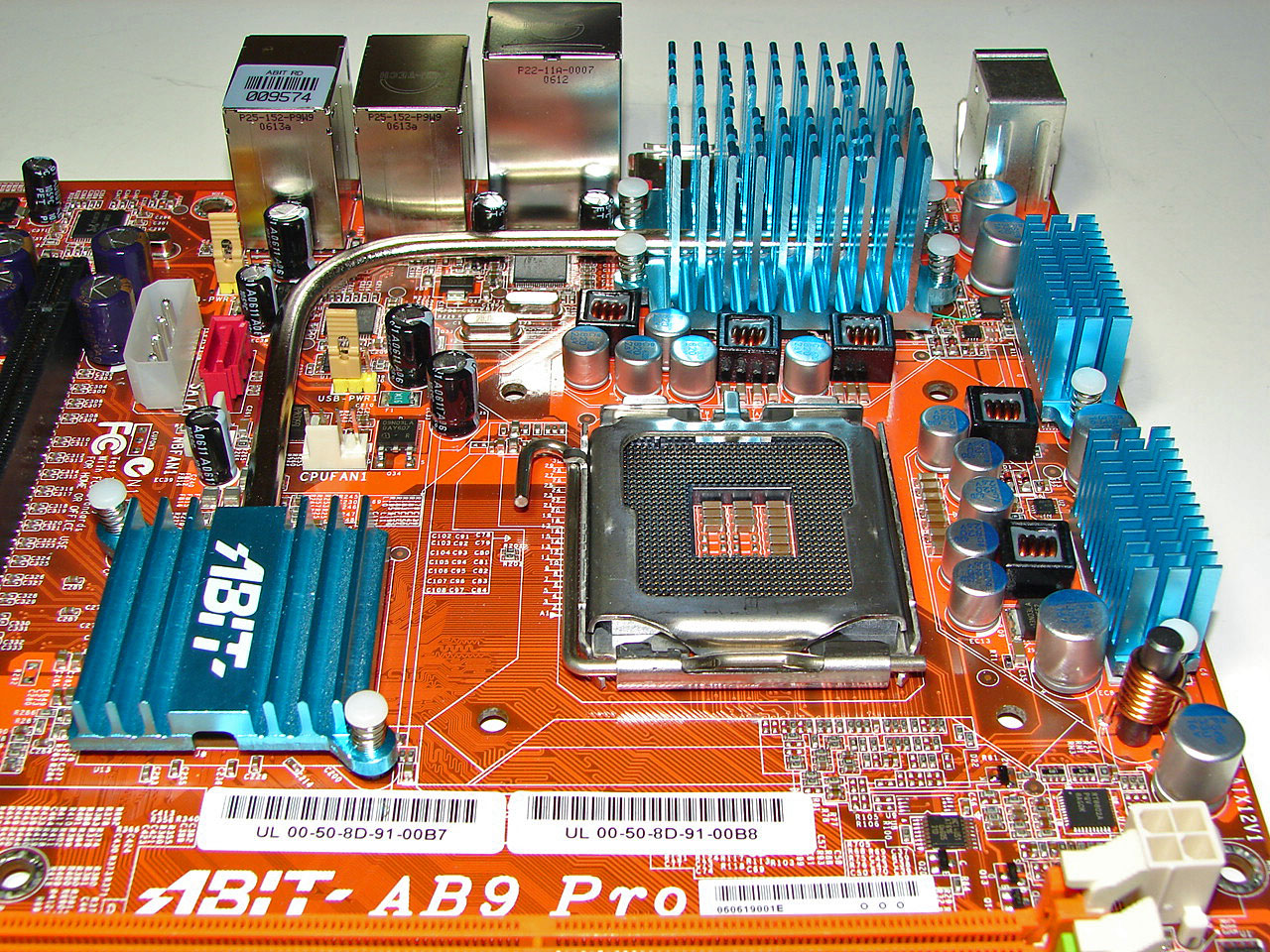
Returning to the CPU socket area, we find an ample amount of room for alternative cooling solutions. We utilized the stock heatsink/fan in our normal testing but also verified a couple of larger Socket-775 cooling solutions would fit in this area during our overclocking tests.
The Intel P965 MCH chipset is passively cooled with a low rise heatsink unit that did not interfere with any installed peripherals. This heatsink is part of the Abit Silent OTES technology that includes a heatpipe system and additional passive cooling for the VRM components. This system kept the MCH cool enough that additional chipset voltage was not a factor in our overclocking tests.

The rear panel contains the standard PS/2 mouse and keyboard ports, LAN ports, and 4 USB ports. The LAN (RJ-45) ports have two LED indicators representing Activity and Speed of the connection through the Realtek RTL8111B Gigabit PCI-E chipset. The audio panel consists of 6 ports that can be configured for 2, 4, 6, and 8-channel audio connections for the Realtek ALC 882D HD codec. The panel includes two S/PDIF (optical in/optical out) ports, and an external SATA 3Gb/s port via the Silicon Image 3132 chipset.
 |
| Click to enlarge |
Abit designed a board that has one of the more interesting layouts we have seen in our labs in a long time. While the board was very easy to install in our mid-size ATX case, we did have some issues with utilizing our optical drive in the top bay due to the location of the JMicron powered IDE port that is located in between the number two PCI Express X1 slot and the number one PCI slot. The Abit board features an excellent voltage regulator power design with high quality capacitors located in each major component section of the board that yielded superb stability with our early BIOS revisions. Our board was able to POST our 805D at 4660MHz but we could not enter Windows due to the inability to change memory timings with the current BIOS. We certainly foresee this board being excellent at overclocking if the BIOS matures properly.
 |
| Click to enlarge |
The DIMM module slots' color coordination is correct for dual channel setup based upon the premise of utilizing different colors for each memory bank. The memory modules are easy to install with a full size video card placed in the first PCI Express X16 slot. The 24-pin ATX power connector is located along the edge of the board along with a series of capacitors for the memory modules. Abit places the four-pin 12v auxiliary power connector at the top of the first memory module but completely out of the way of aftermarket cooling solutions.
The six Intel ICH8R SATA ports are color coded red and are located to the left of the ICH8R Southbridge and battery. The SATA ports feature the newer clamp and latch design. We found the positioning of the SATA ports to be excellent when utilizing either the PCI-E X1 or PCI 2.3 slots. The ICH8R is passively cooled and remained cool to the touch throughout testing.
The first three of five auxiliary fan connectors are located at the bottom edge of the board. The clear CMOS jumper is color coded yellow and is located in between the battery and ICH8R chipset. The CP80P POST port debug LED, chassis panel, µGuru chipset, and red 1394a connectors are located along the left edge of the board. The blue USB 2.0 connectors are located above the SATA ports.
The board comes with one physical PCI Express X16 connector, two PCI Express X1 connectors, and two PCI 2.3 connectors. The layout of this design offers a very good balance of expansion slots for a mainstream board while providing excellent clearance space for graphics card utilization. However, the layout in this area is very unusual if not a bit chaotic. Our main issue is the location of the floppy drive connector at the bottom of the board along with the JMicron JMB363 IDE and SATA ports being sandwiched in between the PCI-E and PCI slots in the middle of the board.
The four-pin molex power connector that will be required for future GPU products and the Silicon Image 3132 SATA port is located above the PCI-E X16 slot. The P965 chipset will not officially support CrossFire or SLI operation so the lack of a secondary PCI-E X16 slot means this board could have been arranged differently. However, Abit informed us that some of the unusual port locations were predicated upon ensuring proper power delivery, stability, and trace layouts based upon the capacitor locations. That may be true, but we think they would do better to add more capacitors and do whatever else is necessary to accommodate a more ideal layout, as frankly the current layout really isn't what we'd like to see.
 |
| Click to enlarge |
Returning to the CPU socket area, we find an ample amount of room for alternative cooling solutions. We utilized the stock heatsink/fan in our normal testing but also verified a couple of larger Socket-775 cooling solutions would fit in this area during our overclocking tests.
The Intel P965 MCH chipset is passively cooled with a low rise heatsink unit that did not interfere with any installed peripherals. This heatsink is part of the Abit Silent OTES technology that includes a heatpipe system and additional passive cooling for the VRM components. This system kept the MCH cool enough that additional chipset voltage was not a factor in our overclocking tests.
The rear panel contains the standard PS/2 mouse and keyboard ports, LAN ports, and 4 USB ports. The LAN (RJ-45) ports have two LED indicators representing Activity and Speed of the connection through the Realtek RTL8111B Gigabit PCI-E chipset. The audio panel consists of 6 ports that can be configured for 2, 4, 6, and 8-channel audio connections for the Realtek ALC 882D HD codec. The panel includes two S/PDIF (optical in/optical out) ports, and an external SATA 3Gb/s port via the Silicon Image 3132 chipset.


33 Comments
View All Comments
Anemone - Monday, July 3, 2006 - link
Yes this is quite interesting, thank you very much Anand and Gary!Things are heating up and getting very interesting. As the windup to Conroe gets underway a lot of folks are out buying mobo's now. I want to see more testing first, not really being yet committed more to the 975 or the 590. Have to be honest and say the 590 is proving to be more than I thought it was, but that's a good thing.
Thus I'm taking all this information in, and am grateful for your previews!
Calin - Monday, July 3, 2006 - link
If the supply of Conroe processors will be much lower than the demand, one can expect the mainboard prices to decrease - if the supply of mainboards will be much higher than the supply of retail Conroe processors. So, buying mainboards in advance might prove a not so good idea.mine - Monday, July 3, 2006 - link
most interesting reading of the last 4 weeksthis 965 vs. 975
thanks anand