The MSI X299 XPower Gaming AC Review: Flagship Fantasy
by Joe Shields on May 9, 2018 8:00 AM EST- Posted in
- Motherboards
- Intel
- MSI
- X299
- Basin Falls
- Skylake-X
- i9-7900X
MSI X299 XPower Gaming AC Visual Inspection
The X299 XPower Gaming AC is listed as an E-ATX sized motherboard though it doesn't exactly fit the specification. The EATX standard specification is 12 x 13-inches, but sometimes OEMs take a bit of liberty with the specification. MSI takes that liberty with this board and it measures in at 10.7-inches wide and 12-inches top to bottom. It will still fit all standard ATX mounting so we do not have any worries on that front, but as it is larger from left to right it will not go directly into strict ATX standards, hence the E-ATX designation.
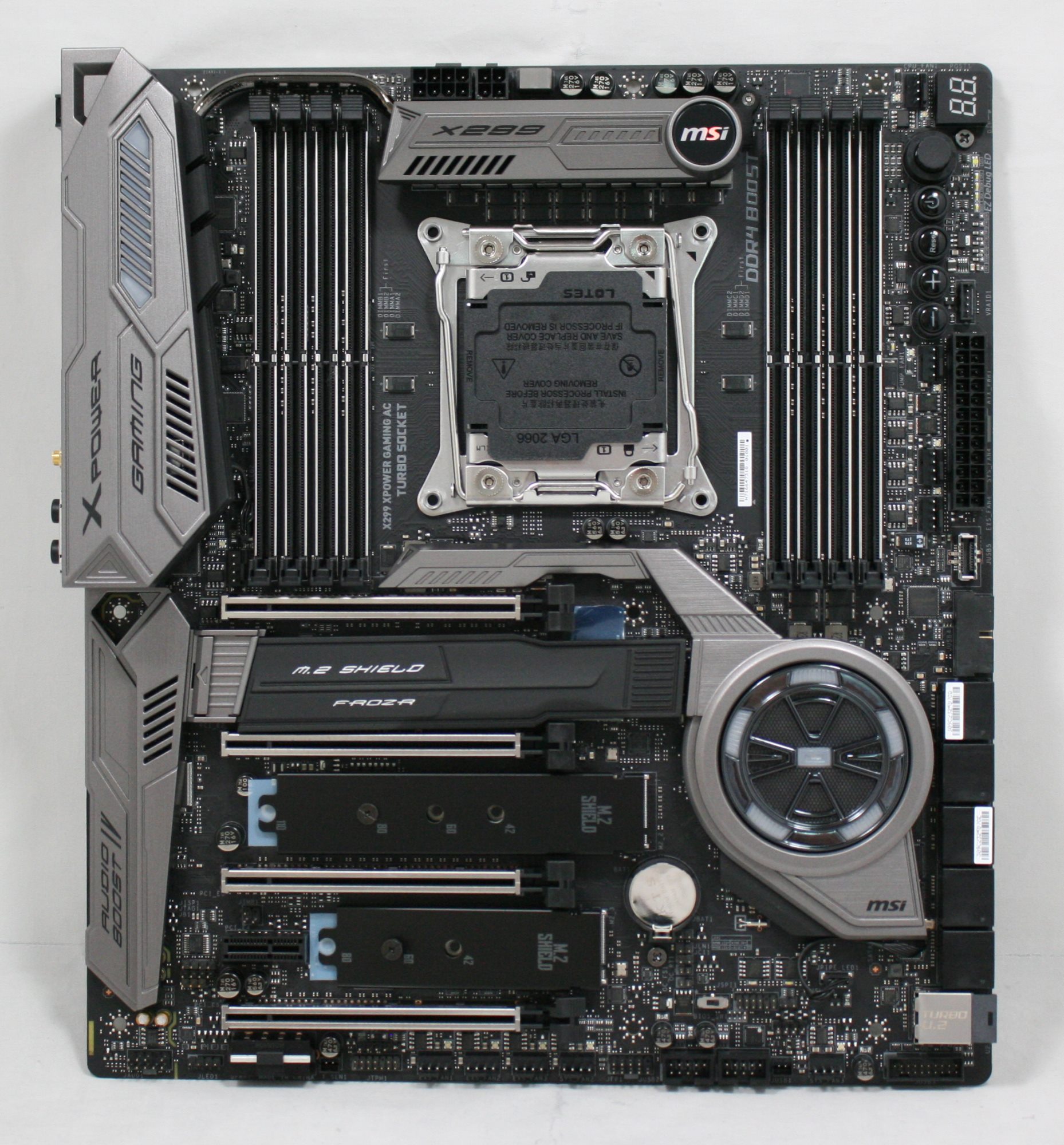
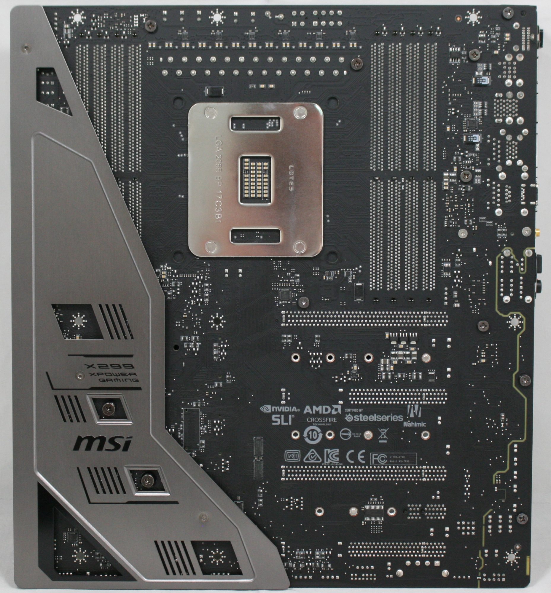
Size aside, the XPower Gaming AC looks like a standard fare motherboard as far as aesthetics go, with a black PCB and grey shrouds all around. On the back of the motherboard, we can see it has a cover on it to increase rigidity.
The board's eight DRAM slots and four full-length PCIe slots are reinforced via MSI's Steel Armor to support heavy graphics cards and also assist with the look. The three M.2 slots all have a heatsink on them, with the bottom two as basic M.2 shields - a thin piece of metal. The top slot uses a larger heatsink, dubbed the M.2 Shield Frozr. The heatsink on the top M.2 slot has a lot more mass to it which should help keep the module underneath cooler than the thinner heatsinks. The M.2 Shield Frozr also has a locking mechanism to keep the hinged heatsink (and drive) securely in place.
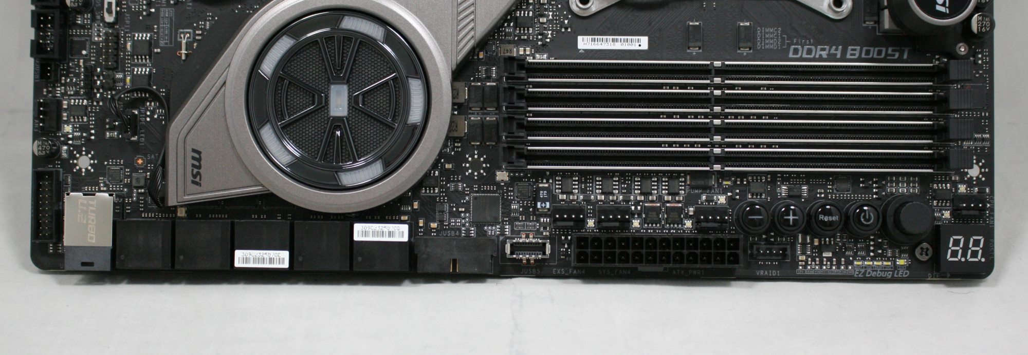
All the shrouds are a gray color contrasting a bit from the black PCB. The chipset shroud looks almost like a reactor core and is one of the locations of the board's RGB LEDs. The other is in the back panel IO shroud towards the top. Outside of that, there are LEDs on the board on the memory slot, to show which are populated. Overall the RGB implementation was minimal but did give the board some character.
The X299 XPower Gaming AC is equipped with a total of 10 headers, each capable of controlling the fans through PWM or DC methods. The fan headers are located on the right side of the board, across the bottom, and one in the middle of the board above the PCIe slot and to the left of the left bank of DRAM slots. MSI documentation doesn't mention the power output of the headers.
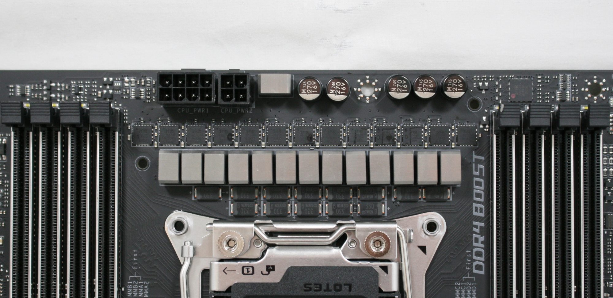
Stripping away the dual heatsinks used to cool the power components, we see a closeup shot of its 14-phase power delivery (12 for CPU). The XPower Gaming AC uses an IR35201 controller in 6+1 phase mode with the '+1' used for CPU VCCSA. This means the six PWM channels are doubled to 12 (IR3599 phase doublers on the back). This yields a total of 13 phases under this heatsink with each phase using an IR3555M 60A fully integrated PowIRstage. For VCCIO, an IR35204, a 3+1 controller, will control the single-phase VCCIO along with a Texas Instruments NexFET CSD87350Q. The memory VRMs are using Primarion PV4210 digital PWMs along with each phase using two 25A/40A NexFETs (CSD87350Q). Delivering power to these ICs is a required 8-pin 12V EPS connector and an optional 4-pin EPS 12V connector. Overall this is one of the more capable power delivery sections we have seen and it has ample cooling with dual heatpipe attached heatsinks.
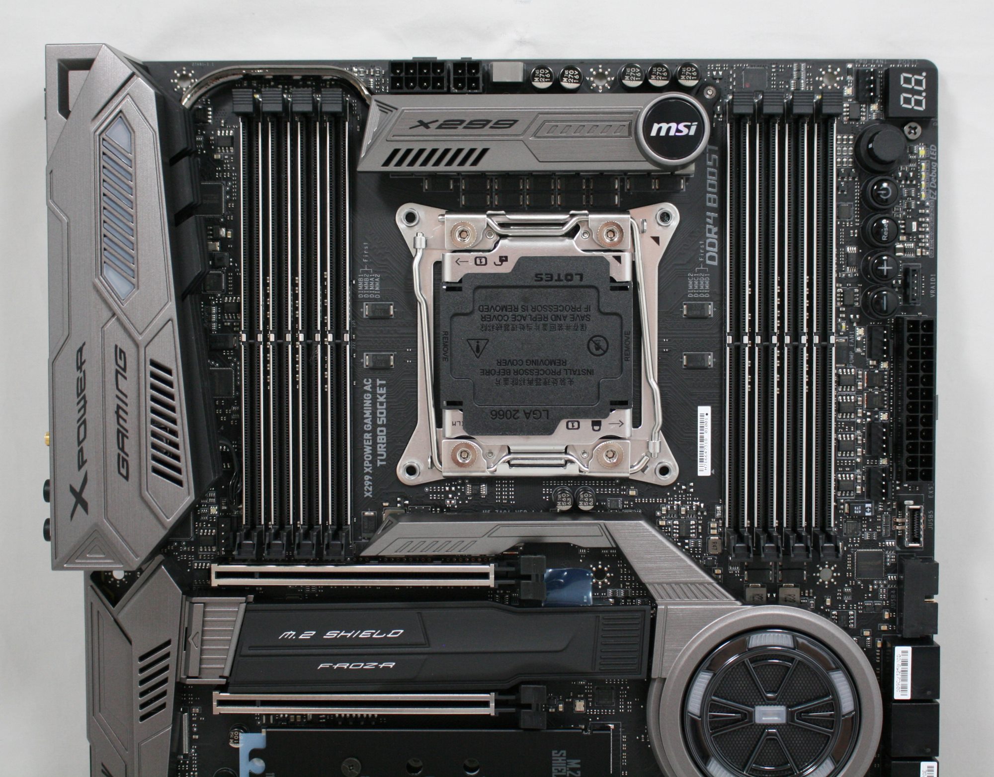
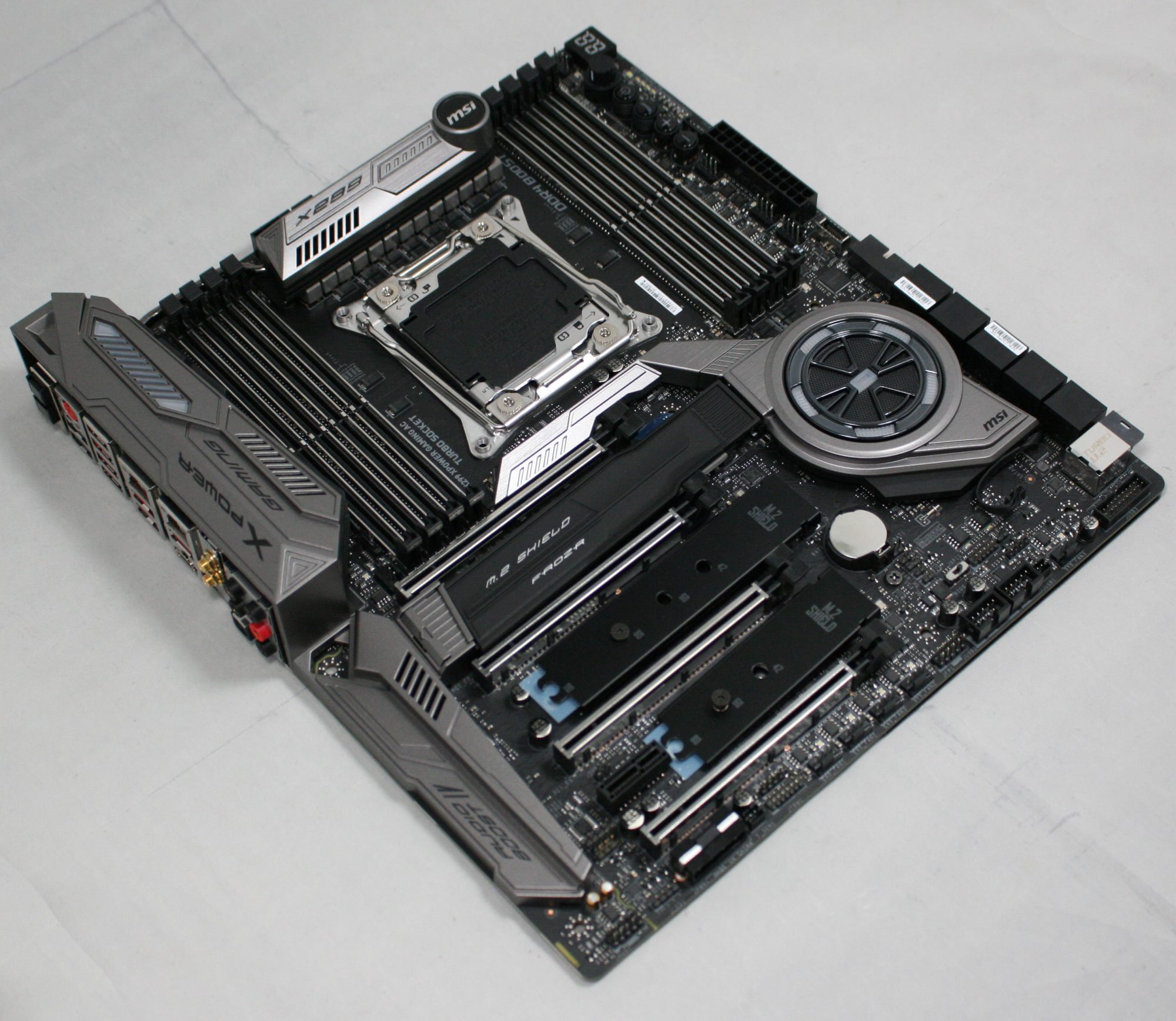
The top half of the board shows our typical arrangement of eight DRAM slots flanking the CPU socket. The 14 total phase power delivery sits above it and is attached to two heatsinks connected via the heat pipe we see snaking above the left DRAM slots and into the second heatsink. The primary heatsink is on the smaller side, but on the other end is something a bit beefier. Combined, this solution worked out well both at stock and when overclocked to 4.5 GHz.
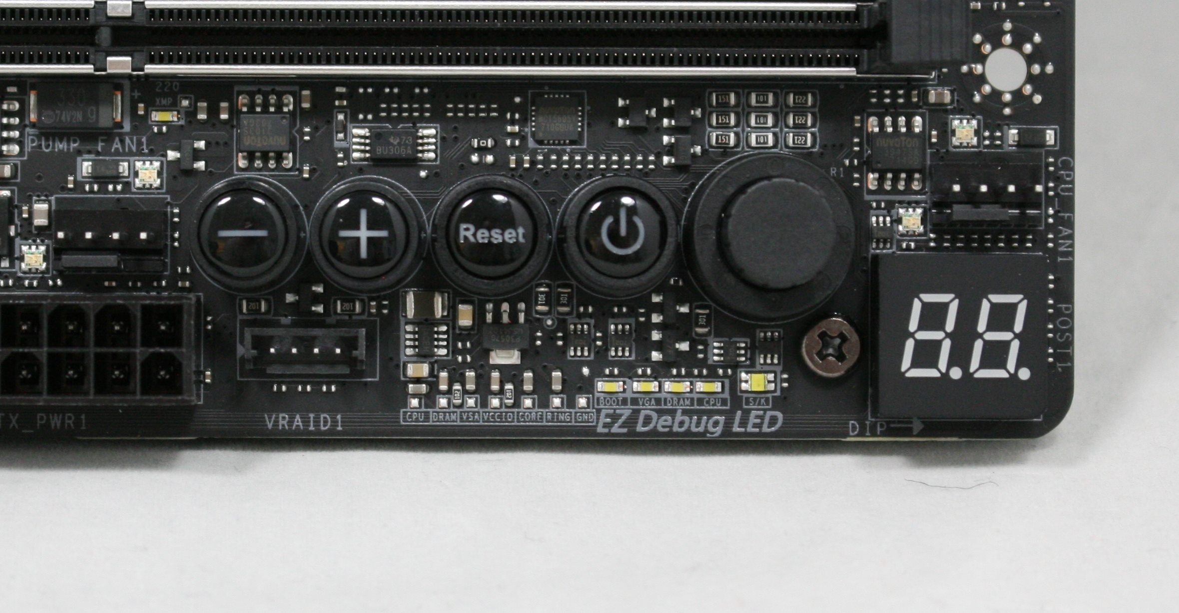
The right side of the board has a host of different gadgets in that area. We can see the debug LED, power/reset buttons and +/- buttons for overclocking BCLK and CPU Ratio on the fly. The EZ Debug LEDs for Boot, VGA, DRAM, and CPU, as well as a 5th LED to show what kind of CPU is in the socket. Also located in this area are the voltage read points and the Game Boost knob.
The right side of the board we are able to see the top of the U.2 port, and its 10 SATA ports on the left side. We can also see a front panel USB 3.0 header and the front panel USB 3.1 (10 Gbps) header as well. Next to it is the 24-pin ATX power connector and the header for Intel VROC. Zooming in a bit on that right-hand corner, the EX Debug LEDs cover CPU, DRAM, VSA, VCCIO, Core, Ring, and also has a grounding pad. Having voltage read points are important when extreme overclocking so users are able to know the exact voltage going into any of the domains. I would like to have seen the read points a lot larger and easier to 'attach'. MSI used to have pins on the read points and a plastic shroud around them which held the ends of the digital multimeter for you and allows leaving them in there.
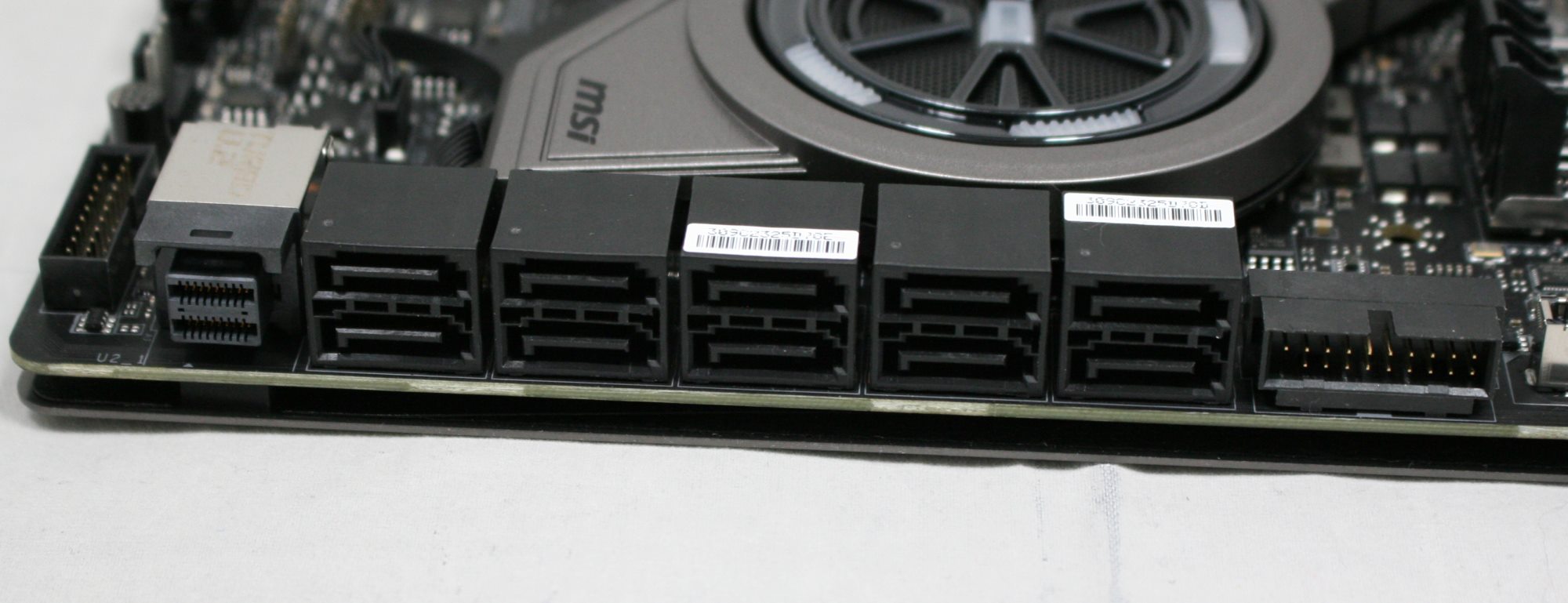
Here we see a closer look at the 10 SATA ports and U.2 port for storage attachment. Eight of the ten ports go through the chipset while the other two are handled by an ASMedia ASM1061 controller. The M.2 ports and SATA ports share bandwidth so some concessions may need to be made when using SATA-based multiple M.2 devices. For example, the first M.2 slot (with the large cooler) will render SATA1 disabled while the rest are enabled. The second and third slots are a bit more complicated. I have included an image of the combination table from the manual in the gallery.
For the three onboard M.2 slots, despite the first slot being with the large cooler, it is actually powered through the chipset, as is the second slot. Only the third slot comes from the CPU, in some configurations being switched with the PCIe lanes in the bottom slot as demonstrated in the table below.
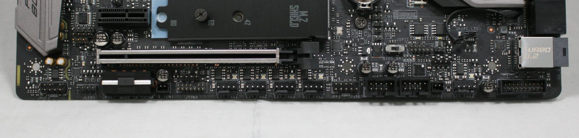
Across the bottom of the board are the headers. Located just above the USB 2.0 headers is the BIOS switch for its dual BIOS capabilities, the direct to BIOS header, as well as the slow mode switch.
From left to right we have:
- Front Panel Audio
- RGB LED connector
- Molex Power (supplement PCIe power)
- Thermal Sensor header
- TPM Module connector
- 4 x Fan headers
- Front Panel connector
- 2 x USB 2.0 headers
- LED Light demonstration power header
- System Fan header
- Front Panel USB 3.0 header
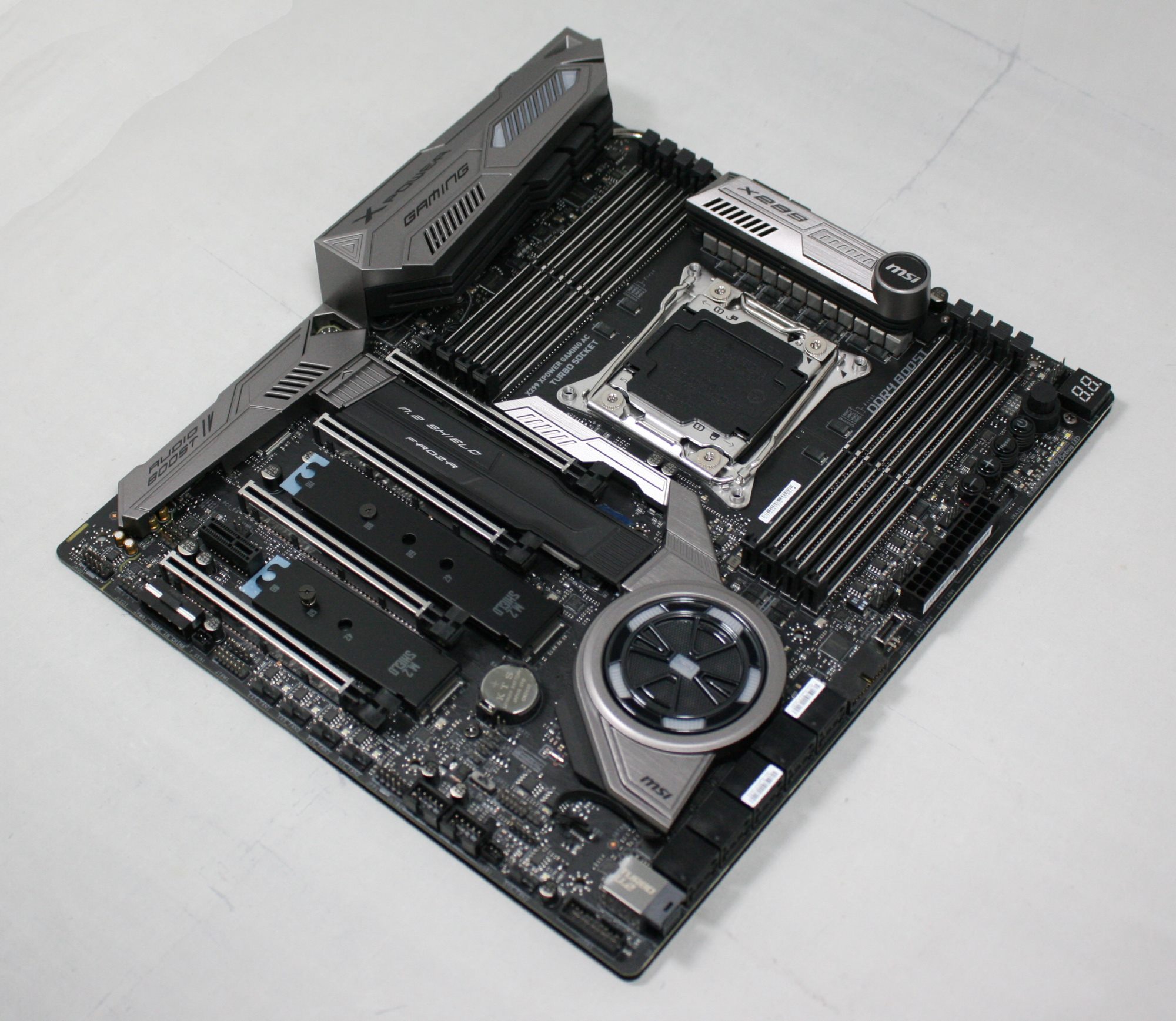
The bottom half of the board shows off the reinforced PCIe slots and the M.2 Shield Frozr on the first M.2 slot. We can see shrouding covering the Realtek ALC1220 codec and its Chemi-con audio capacitors. The board also separates audio from the rest of the board, as well as separate PCB layers for left and right channels. For headphone users, there is a dedicated headphone amplifier which auto-detects impedance, up to 600Ω.
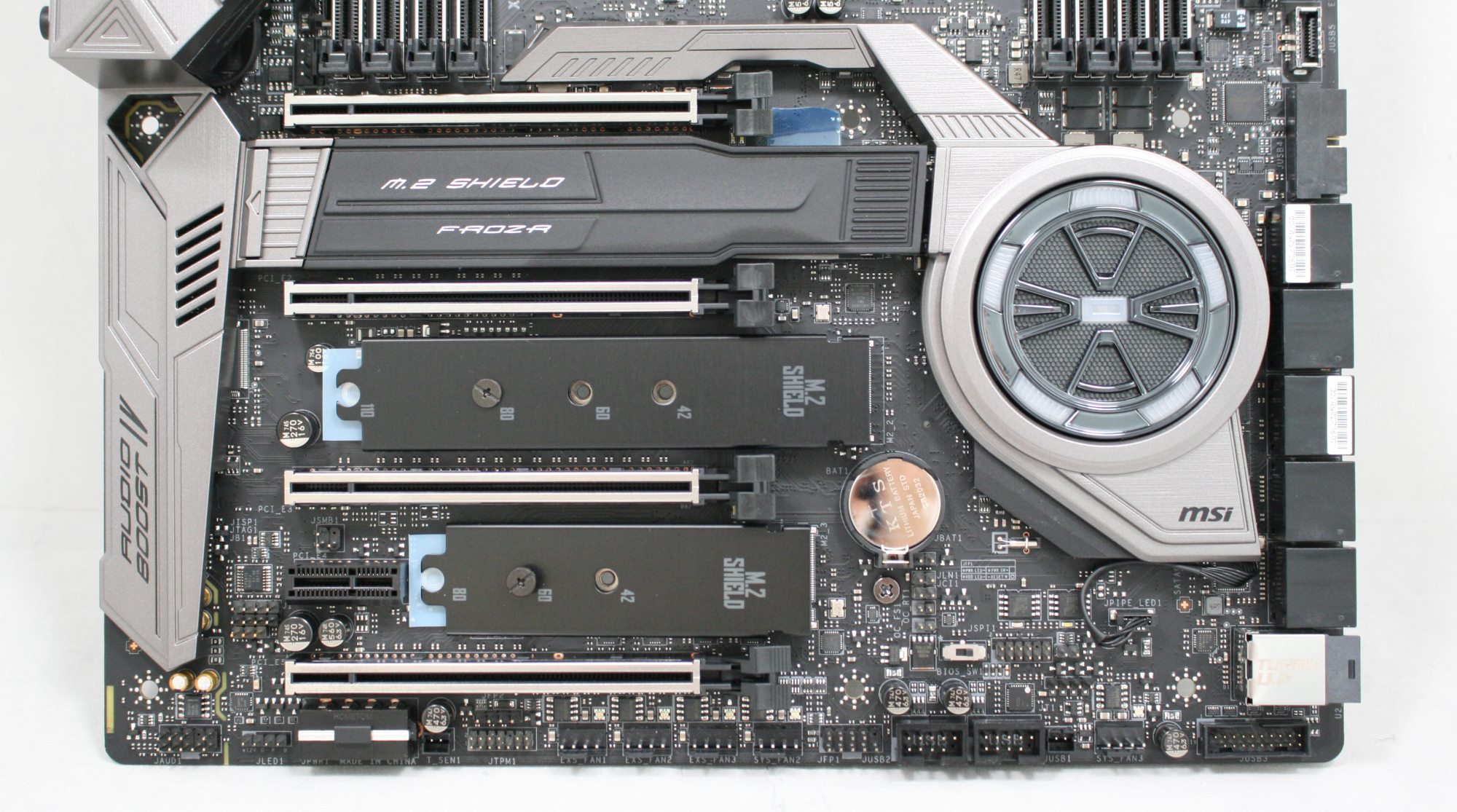
There are a total of five PCIe slots, four full-length and CPU connected, while the single PCIe 3.0 x1 slot is connected via the chipset.
Below is a simplified list of how the PCIe slots will work with each family of CPUs (talking PCIe lanes) when multiple cards are used (the "@" symbol is used to show slot preference for the configuration):
| MSI X299 XPower Gaming AC CPU PCIe Layout | |||||||||
| 44-Lane 1/2-Way |
44-Lane 3-Way |
44-Lane 4-Way |
28-Lane 1/2-Way |
28-Lane 3-Way |
16-Lane 1-Way |
||||
| PCIe 1 | @x16 | @x16 | @x8 | @x16 | @x8 | @x8 | |||
| PCIe 2 | - | - | @x8 | - | @x8 | - | |||
| PCIe 3 | @x16 | @x16 | @x16 | @x8 | @x8 | x4 | |||
| PCIe 5 | x8 | @x8 | @x8 | x4 | - | x4 | - | x4 | - |
| M.2_3 | x4 | x4 | x4 | - | x4 | - | x4 | - | x4 |
| SLI | Yes | Yes | Yes | Yes | Yes | No | |||
| Crossfire | Yes | Yes | Yes | Yes | Yes | No | |||
The back panel IO has the following connectors:
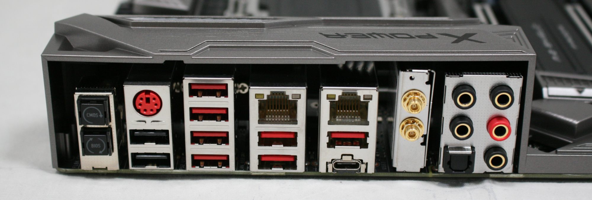
- 1 x Clear CMOS
- 1 x BIOS Flashback+ button
- 1 x PS/2 Keyboard/mouse combo port
- 2 x USB 2.0 ports
- 1 x BIOS FLASHBACK+ port
- 2 x Wi-Fi Antenna connectors
- 6 x USB 3.1 (5 Gbps) ports
- 2 x LAN (RJ45) ports
- 1 x USB 3.1 (10 Gbps) Type-A port
- 1 x USB 3.1 (10 Gbps) Type-C port
- 1 x Optical S/PDIF OUT connector
- 5 x OFC audio jacks
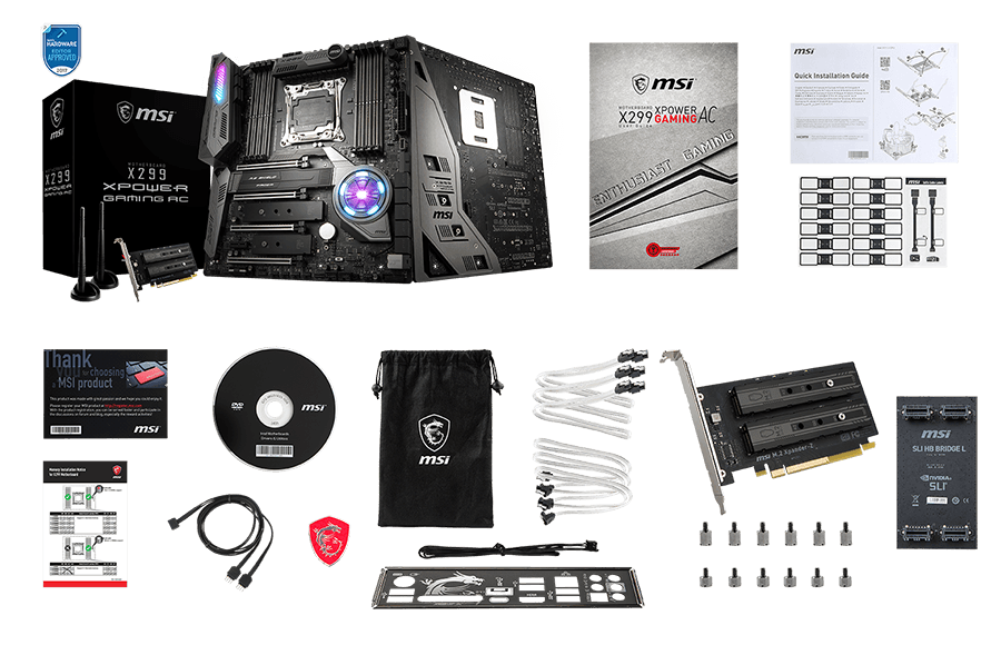
In the Box
The MSI X299 XPower Gaming AC includes the following accessories:
- Driver & Utilities Disk
- Motherboard User Guide
- 4 x SATA cables
- IO Shield
- SLI HB Bridge M
- 1 x 1 to 2 RGB LED Extension Y Cable (80cm)
- Quick Installation Guide, SATA Labels, Manual
- M.2 XPander-Z PCIe Riser Card
- Case badge
- 2 x Antenna


17 Comments
View All Comments
The_Assimilator - Thursday, May 10, 2018 - link
"Five total M.2 slots with full bandwidth? Check."Last time I checked, three and five were not equivalent.
Ket_MANIAC - Thursday, May 10, 2018 - link
Last time I checked, Anand still worked here. Sad!The_Assimilator - Friday, May 11, 2018 - link
Yeah, back before this site's proofreading took a Purch to the knee.PhrogChief - Friday, May 11, 2018 - link
I mean... "GAMING" on everything now? Seriously... I thought playing games was just ONE of the things us PC enthusiast types do with the computers we build...What ever happened to -PRO, or -DELUXE, or WORKSTATION, boards, etc... Now everything is for GAMING! GAMING HEADPHONES!!! Same as the nice studio monitors, just now with HIDEOUS COLORS AND LIGHTS!!! Fcuking shoot me...
Diji1 - Sunday, May 13, 2018 - link
OK, OK, no need to get histrionic about a non-existent problem.blingon - Friday, May 11, 2018 - link
> The chipset shroud looks almost like a reactor coreActually, it really doesn't.
jackmiller5623 - Wednesday, June 24, 2020 - link
The printer test page allows you to check the printing capacity of your printer and also make the test for free.Print test page provides you the facility to make the dream come true of printing the page absolutely free. Print a new page from your new printer and get the page free for you to check and print your lovely documents here at- https://printertestpage.co/.