ECS 755-A2: Performance and Value for the Athlon 64
by Wesley Fink on January 30, 2004 8:51 AM EST- Posted in
- Motherboards
ECS 755-A2: Board Layout
The ECS 755-A2 is a little less than full-size, mounting in the case with 2 rows of standoffs instead of the 3 seen on full-size ATX boards. This should make it an easy fit in almost any case. The disadvantage is that the smaller size often requires compromises in component placement.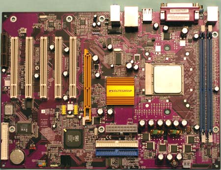
The 755-A2 is the same dark plum color used on the 755-A. Like the SiS 755 Reference Board, the processor socket is turned and the DIMM slots are placed at the very top of the board. Most heatsinks have fins arranged across the short dimension of the 754 socket, including AMD's own HSF included in retail CPU kits. With heat rising, this places the DIMMs in the hottest position on the board in a common tower case. This did not present a problem in our testing, but should be kept in mind when cooling a system based on the 755-A2.
The ECS only has two 3-pin fan connectors. Those hoping to add an active North Bridge cooling solution will not find a fan connection near the 755 chip. With many power supplies having a 3-pin monitoring connection for the power supply, another fan connection would be welcomed. The CPU fan connector is near the CPU socket, but the only other connector is between the 5 PCI slots and the backplane.
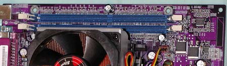
The 755-A2 is single-channel Socket 754, so it only requires one DIMM. However, most Socket 754 boards provide 3 DIMM slots. With the many problems that we have found with actually using 3 DIMMs on Athlon 64 boards, including just 2 DIMMs will not likely compromise memory expansion and probably cuts down on Technical Support calls to ECS. The maximum memory capacity is the same 2GB as in other boards, and two 1GB DIMMs can reach that maximum.
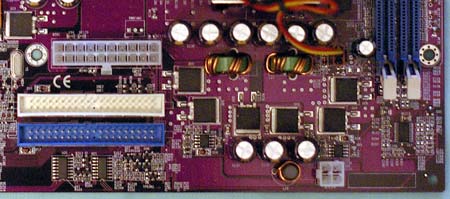
Unlike Athlon XP motherboards, the Athlon 64 and FX51 boards that we have seen use a standardized ATX plus 12V connector arrangement. This is identical to the power connector requirements of current Pentium 4 systems. ECS places the connectors in the preferred upper right of the board. In general, the arrangement of external connectors along the right edge of the board should work well in most cases.
The board appears to be a 3-phase design, based on the 6 power transistors used, but with only 2 coils we are not sure. There were no problems with power regulation in our testing.
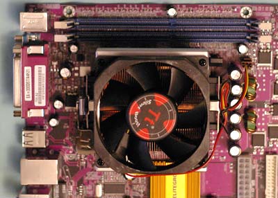
While there was no problem fitting a standard heatsink/fan like the AMD Athlon 64 retail HSF, the memory sockets are too close to the CPU to mount a large HSF like the Zalman. The very tall capacitors to the right of the socket could also block some of the larger HSF designs. We suggest that you look carefully at the available space if you plan to mount a very large HSF on the 755-A2.
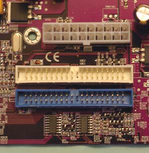
The Primary/Secondary IDE connectors are all in our preferred position, above the midline of the board and to the right of the board. This position on the top right edge of the board works well with cable arrangements in almost any case. With the 20-pin ATX connector located between the IDE connectors and the North Bridge, it is easier to first connect the IDE, then the bulky ATX power cable.
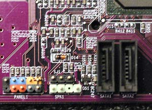
It is difficult to see in a picture, but the ECS SATA connectors are much better than we usually see. The fragile SATA connectors are in a full socket that makes accidentally stressing the connector and breaking off the connector a lot less likely. With frequent board and cable swapping, you come to appreciate how fragile the SATA connector design really is. We've actually broken connectors on 4 SATA drives/boards so far compared to none with many IDE drives. The ECS socket design looks much sturdier. SATA hard drive manufacturers should really take a close look at this socket design.
While this is definitely a value board, ECS still includes a color-coded front panel connector to make identifying connections a little easier.
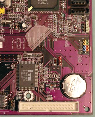
Unfortunately, the floppy connector is located on the lower right of the board. This will work fine in some case designs, but it will be a difficult reach in large tower cases. This location can also make neat cabling difficult in most cases. In fairness to ECS, this placement is carried over from the SiS 755 Reference design. While smaller than the Reference board, the 755-A2 follows the reference design, including both the good and the bad. It will be interesting to see what Asus does in the layout of their 755 board.
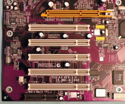
ECS includes 5 PCI slots, an 8X AGP, and a CNR slot. With memory at the top of the board, there is no concern about interference with the AGP slot. The slot area was well thought out, with little to interfere with mounting expansion cards.


14 Comments
View All Comments
KillaKilla - Friday, January 30, 2004 - link
NFS4- I agree, newegg support/ruturning is quite excelent.When is the Asus version coming out? They're generally better than ECS.
Why did they use the 9800Pro-128? Why not the XT? I would think that to test the MB/CPU combo you would want to eliminate as much of other bottlenecks as posible.
gglawits - Friday, January 30, 2004 - link
When one clicks the "Buy it from ioCombo for $84.95" link, what comes up is the 755-A, not the 755-A2.Some people might not notice the difference and order the old 755-A anyway. Major goof-up.
Either remove that link altogether or make it point to a 755-A2.
microAmp - Friday, January 30, 2004 - link
What board did you get in replacement NFS4?I returned my ECS board back to NewEgg too and settled for the ASUS K8V.
NFS4 - Friday, January 30, 2004 - link
After getting burned with "DDR333 only" support on my 755-A (even after ECS plastered stickers on the box and specs on the website claiming DDR400 support), I won't be going with them any time soon.Good thing NewEgg took back my board even though it was past NewEgg's 30 day warranty period. Shows you what a good company NewEgg is and how they look out for their customers. ECS, are you listening?