More Than Throughput: Next Generation Wi-Fi Testing with Ixia's WaveDevice
by Joshua Ho on March 25, 2016 8:00 AM ESTWi-Fi Basics: L1/PHY Layer
While most of our readers will have likely used Wi-Fi for the better part of two decades - and in my case it has essentially been around most of my life - in practice few people at all know that much about how Wi-Fi works, even within technical circles. Overall, Wi-Fi is a deceptively complex topic for those that are unaware of how it works, as it extends far beyond simple radio transmission principles, especially with the most recent iterations of the technology. Some knowledge can definitely be transferred over from LTE and other cellular technologies, but Wi-Fi is a very different technology in the sense that much of the intelligence has to stay on the device, as opposed to being supplied by a base station or access point. For the most part it’s up to the device to decide what the right physical link rate is based upon the RF environment, when to transmit data, how to roam between access points, how and when to use power save mechanisms, and to proper connection setup between the device and the access point.
Source: Wikipedia By Chetvorno - Own work, CC0
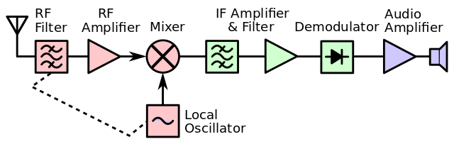
To understand Wi-Fi, we can start at the physical link layer, or Layer 1/L1. Anyone who has done some studying of how radios work will probably see a lot of similarities here as in general every Wi-Fi combo chipset that will ship in a phone is going to have a superheterodyne radio. At a high level, a superheterodyne radio is basically a radio that uses frequency mixing in order to convert the incoming signal to a different frequency to make the signal easier to process.
In the case of this kind of radio, the RF front end on the receive side contains filters, a low noise amplifier to get very weak signals up to usable levels, and a mixer is then used in conjunction with a local oscillator to get the incoming waveform from the signal frequency down to the carrier frequency. There are also likely to be some more filters and amplifiers after the local oscillator as the circuit is dealing with an electric signal (AC) at a much lower frequency, as while it’s pretty easy to get a transistor to switch on and off at 10 MHz it’s pretty much impossible to do the same thing at 60 GHz. From here, the signal can be converted from analog to digital, and also brought down to baseband frequency. For those that aren’t familiar with signal processing, baseband is effectively the frequency from 0 Hz up to the maximum signal frequency (which for Wi-Fi is often going to be the channel width, ranging from 20MHz to 80MHz). When the signal is at baseband, it’s possible to do a lot of signal processing that would otherwise not make a lot of sense, like Fourier transforms.
![]()
Source: Microwaves & RF
On the transmit side, Wi-Fi continues to look relatively similar at the physical block diagram level when compared to pretty much every commercial radio design since the 1940s. Starting at the modem, data is encoded from a digital bitstream into a baseband signal. This signal is then amplified appropriately, upconverted to the signal frequency with the local oscillator again. At this point we're back to the passband frequency that the radio will transmit at. Before the signal is transmitted though, it is fed through more amplifiers like a driver amplifier and filtered again. The signal is amplified again through the power amplifier to get up to a reasonable transmit power for the receiver before it is transmitted through the antenna.
Source: Wikipedia, Bob K
This technically what enables the physical link layer to work, and any issues here can really cause everything to fall apart. In the case of 802.11ac physical layer, the signal is encoded into the carrier using modulation anywhere from BPSK up to 256QAM. We have discussed this before, but the short story is basically that a sinusoidal signal can be decomposed into two sinusoids that are out of phase by a quarter of a period.
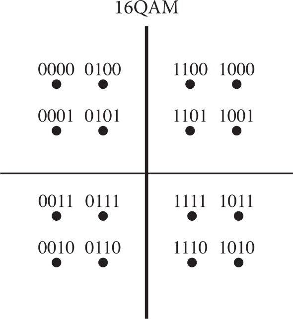
By varying these two components, it’s possible to generate an infinite number of points that represent a binary encoding. Of course, this is limited by the noise present in the received signal, which turns points into a probabilistic cloud.

Source: Keysight Technologies
In addition to this varying of phase, Wi-Fi also splits the channel into narrow subcarriers to maximize throughput. This technique is known as orthogonal frequency-division multiplexing, and is used in a number of technologies like LTE as well.
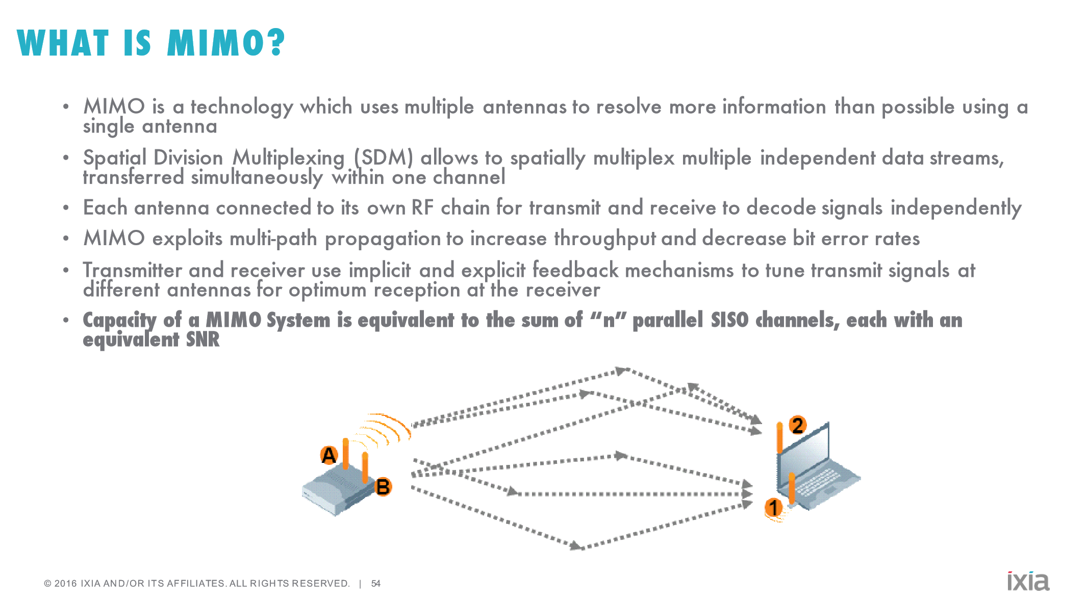
The other technique that is worth knowing about is Mulitiple Input and Multiple Output (MIMO) and Multi-User MIMO (MU-MIMO). In both cases, multiple antennas are used to enable additional throughput by utilizing multipath transmission. MU-MIMO in turn takes this a step further by using precise beamforming in order to spatially multiplex transmission and reception. While the concept is relatively simple, actually implementing this is difficult to say the least, which is why MU-MIMO Wi-Fi implementations have only been shipping for about a year or so.
Source: 3G4G Blog, NTT
This aspect of Wi-Fi is known as the Physical Medium-Dependent layer, or PMD layer. There are more aspects that could be discussed regarding the physical link layer, but in the interest of not making things any more confusing we’ll stop here and talk about what aspects of the physical layer WaveDevice is actually capable of testing. With every packet, WaveDevice is capable of reporting a number of statistics about what’s happening at the physical link layer. Importantly, this includes the constellation error, by showing the average magnitude of the deviation of the actual I/Q position relative to the theoretical I/Q position for a given encoding. It’s also possible to look at how well the device is constraining its transmission to specific bands/channels, and whether the device is transmitting excessive levels of power, although transmit power limits is really more the realm of FCC compliance than anything else.
As a result, when we’re looking at relative Wi-Fi performance, we can actually start to make determinations about whether the problem with a device’s Wi-Fi performance is because it’s just not transmitting data properly and causing data corruption, or if it’s something happening at the software level. While the physical layer is critical, if you subscribe to the OSI model of networking then there are six layers above it that need to work as well to make sure that your cat pictures load as they should. So next we'll take a look at the data link layer to better understand how Wi-Fi works and what WaveDevice is capable of testing there.


44 Comments
View All Comments
Ryan Smith - Friday, March 25, 2016 - link
Correct, it's the 12.9" iPad Pro.plext0r - Friday, March 25, 2016 - link
Excellent article! Thanks for the write-up using professional-level WiFi testing.jardows2 - Friday, March 25, 2016 - link
Very interested to see this in use. In my work, I daily have to deal with people's wi-fi problems, and to see some of the insights this tool can use will be very enlightening. Trying to fix people's wi-fi over blind phone support is an excercise in frustration!Ravn - Friday, March 25, 2016 - link
Excellent stuff Anandtech. WiFi is usually in the specifications described by : WiFi: Yes, Bands: 2.4/5GHz a/b/c/g/n, Maximum throughput: xxx Mbps. And it says just about nothing about the quality in the WiFi unit. Finally some relevant RF data that describes how the WiFi performs in real life. Thank You!An additional test that could broaden the relevans of the WiFi testing, could be how the WiFi unit performs with a lot of BlueTooth units in the same area. BT's nasty frequency hopping nature in the whole WiFi band results in a lot of problems in WiFi setups. How the WiFi units handles this could be very interresting to include.
zodiacfml - Friday, March 25, 2016 - link
Awesome and powerful testing machine you have there. One "Small" Wi-Fi testing website that I read regularly would be interested too. Yet, too powerful that only electrical engineers would use most of its functions.If I'm correct, you posted before that this device can also test for MU-MIMO performance without too much difficulty. Wi-Fi AP and routers reviews on Anandtech in the future wouldn't hurt? :)
On a second thought, I think there is a brighter future for 802.11ad than say, MU-MIMO. As long it is line of sight or no obstruction, 1 Gbps is easy for this standard.
name99 - Friday, March 25, 2016 - link
You've left out some interesting aspects of the physical layer.An essential part of this layer is the Forward Error Correction (FEC), which augments the transmitted data with additional data in such a way that if a few bits in the stream are in error, they can be recreated from the remaining bits (think parity on steroids).
These error correcting codes have been improved over the years in successive specs as it's become feasible to throw more computation at them, with the current state of the art being so-called LDPC (low density parity code). [These same codes are currently used by a lot of flash vendors, but have a theoretical problem(trapping sets) that limits their effectiveness above certain noise levels, so better alternatives have been proposed (but as far as I know are not yet in production) for flash, and likely will follow in the next big WiF spec.]
The specifically interesting thing about these codes, in the context of this article, is that it's not THAT useful to simply say that a chipset implements LDPC (or some other FEC). Implementing the encoding is a fixed algorithm that you can't really get wrong, but there are many ways of implementing a decoder (in other words, ways of attempting to construct the correct data stream from a corrupted data stream). These methods, of course, differ in the power they require, how much computation they utilize, how long they take to correct errors, and how complicated they are to implement.
The real difference in performance of different chipsets (at the L1 level) is in how well their FEC decoders work. That's where the magic lives.
At the next level up (the MAC level) its is crazy how much performance is lost because of the decentralized/unco-ordinated nature of the media access protocol.(This is the CSMA/CA that the article mentions.)
Even in the simplest real world case of one base station and one device, you're losing 35% or so of your goodput to the MAC protocol, and it rapidly drops to 50% and then worse as you add just a few devices. The successive specs have tried various schemes (primarily using the logical equivalent of very long packets) to limit the damage, but all this has done is really keep things standing still so that the situation in each successive spec is not worse than in the previous spec. LTE can be vastly more efficient because it provides for a central intelligence that co-ordinates all devices and so does not have to waste time on guard intervals where everyone is looking around making sure that no-one else is talking or getting ready to talk.
I don't understand why 802.11 has been so slow to adopt this model; putting the controlling intelligence in the base station (or base station equivalent in a peer network) and having every other device act as a slave. They're going to HAVE to go there at some point anyway --- they've pretty much run out of every other performance option --- and avoiding doing so in 802.11ac just means five more years of sub-optimal performance.
[You can see this in the iPad Pro numbers. The BCM4355 supports 80MHz channels, and so a maximum PHY rate of 866Mbps, But the best you see is just under 600Mbps (and that performance is only available when transmitting extremely large packets in only one direction); the gap between this and the PHY rate is because of time wasted doing nothing but sitting around following the MAC protocol. This disappointing goodput compared to PHY rate is not due to the mythical "interference" that is blamed for every random radio issue; it is due to the design of the MAC protocol.
You also see performance fall as the received signal strength falls. This performance drop is ALSO not due to interference, unless you want to make that word meaningless. The correct term for this performance drop is that it is the result of noise, or more precisely a falling SNR (signal to noise ratio). As the signal to noise ratio falls, you can pack fewer bits into each fragment of time (ie you have to switch from using QAM256 down to QAM64 down to QAM16) and you have to use more of those bits as error correction bits rather than as actual data bits.]
Denbo1991 - Friday, March 25, 2016 - link
802.11ad and 802.11ax will have some centralized scheduling features to cut down on the overhead you talk about, especially in the context of many devices on one AP or many overlapping APs.zodiacfml - Saturday, March 26, 2016 - link
There's way a lot more to talk about here than possible.alanore - Saturday, March 26, 2016 - link
Definitely some good points that should be covered. It might be worth covering how older low speed devices can consume a large proportion of the air time and thus performance.Also in the article it might be worth calling out spatial streams and how they effect performance. In the article it was an apples for apples comparison (2x2 Vs 2x2) but I guess soon we might see a poorly performing 3x3 laptop getting similar results to the iPad pro.
Ratman6161 - Monday, March 28, 2016 - link
Interesting but....for most of us does it really mean anything? So an iPad can achieve 600 Mbps throughput. How does this help me when wireless is used nearly exclusively for accessing the internet and my ISP provides 60 Mbps? For home use, I'm more interested in how well are things working when I have my Android TV streaming an HD Netflix movie while in the other room my wife is doing the same on Amazon and we are also both web surfing on either a tablet or a laptop...and that's more about the router than the individual devices, isn't it?Even at the office, no one is doing anything that requires 600 Mbps or even the 300 of the Pixel C (and the connection in/out of our building is only 20 Mbps). Its more a question of how many devices we can get connected simultaneously at a reasonable/usable speed.