AMD Thunderbird & Duron Overclocking Revealed
by Anand Lal Shimpi on July 19, 2000 3:54 AM EST- Posted in
- Guides
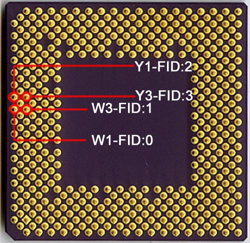
We already know the four FID pins from Tom’s first Socket-A Overclocking article, the pins are W1, W3, Y1 and Y3 which can be seen in the picture below:
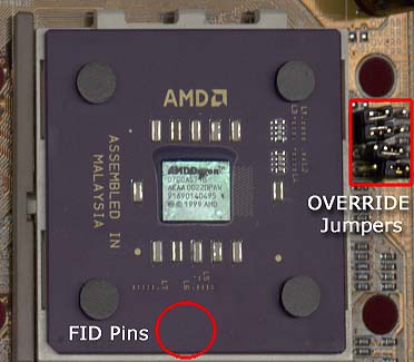
The first thing we noticed when we found the ‘OVERRIDE’ jumpers on our AZ-11 was that these four pins are nowhere near the ‘OVERRIDE’ jumpers, which made very little sense to us at the time since it would require FIC to route the traces (which were visible on the top layer of the PCB) essentially around the socket before making the way to those pins; it would’ve been much easier for FIC to plant the jumpers on the side of the socket closest to the FID pins.
Here’s where Tom Shaver’s suggestion that the FID and BP_FID pins both must be controlled comes into play. If the four ‘OVERRIDE’ jumpers weren’t close to the FID pins of the CPU, maybe they were actually controlling the BP_FID pins on the CPU?
In order for that theory to hold up, two things are required: 1) the BP_FID pins on the CPU would have to be close to the actual ‘OVERRIDE’ jumpers on the AZ-11 board, unlike the FID pins which are a decent distance away from the jumpers and 2) the BP_FID settings would have to be identical to the FID settings (since we thought that we were controlling the FID settings and used the FID settings from AMD to adjust the clock multiplier of our CPUs).
In order to confirm the first condition, we would have to test each and every pin to find out if it actually was a BP_FID; luckily, someone already took care of that for us. One of the best sites in our community (at least in our opinion), Ace’s Hardware, has been known for having an extremely technical message board. A poster on their board, John C. discovered the four undocumented BP_FID pins on the Thunderbird/Duron.


0 Comments
View All Comments