Silverstone Zeus 1200W: Designed for the Power Hungry
by Christoph Katzer on July 7, 2008 2:00 AM EST- Posted in
- Cases/Cooling/PSUs
The Inside
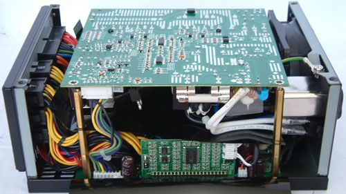
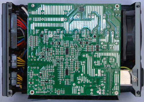
The housing is easy to open and with the top plate removed we can see the back of a PCB. Now it's clear why Silverstone needed to stick to an 80mm fan because the sandwiched PCB design doesn't allow the use of a larger fan. Sandwiched PCBs (i.e. two PCBs with all the components on the inside) are becoming a more and more common design these days; the Antec Signature Series we just tested also used this approach. In general, one can say that the designers leave the filtering stage and the primary stage with mostly AC-voltage on one PCB and the second one carries the secondary stage with DC voltage only. Due to a lack of space, the standby rail also usually resides on the first PCB.
Let's return to a problem we mentioned earlier regarding multiple vs. single 12V rails. After a user has scratched away the white sticker on the side of the power supply he will recognize that his warranty is gone and it didn't even help further since the manufacturer placed a plastic sheet behind the sticker, making it impossible to reach the little switch. You need to open the power supply to use this switch, which is quite unfortunate. During testing we had several problems with the 17A on the 12V rails, which led us to the point that we combined all of the 12V rails into one and our load problem was gone. The problem is that Silverstone doesn't mark the 12V wires on each harness to differentiate the 12V rails, so the user/reviewer is unable to see immediately which 12V rail is being connected to the what components (or in our case, the programmable load). Most end-users will not need to worry about this problem, as 17A per 12V rail should be sufficient. You may need to juggle a few connections if you somehow manage to create a 1000W or higher load, but the multiple PEG connections already address that to a large degree.
First PCB
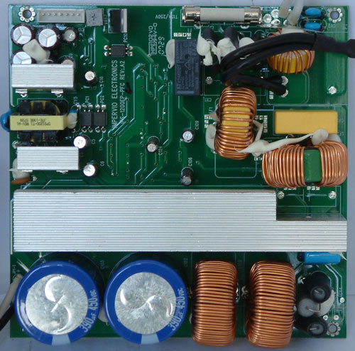
The first PCB in this PSU carries the filtering stage, the primary stage, and the standby circuit. The filtering stage is easy recognizable through its fuse on the top, several caps, and coils. The rectifier bridge is hiding under the heatsink on the right side. There are two large coils and two main-caps, as the designers couldn't place one single large cap due to the reduced possible height. The two caps are identical and come from Hitachi, both rated at 390µF and 450V, which is well within feasibility. The upper left side features the standby circuit with its own small transformer. Besides the circuitry we see the name Impervio printed on the PCB, which is a familiar name with Silverstone power supplies. Even though this power supply still seems to be produced by IS Quasar; the designer is Impervio in cooperation with Silverstone.
Secondary PCB
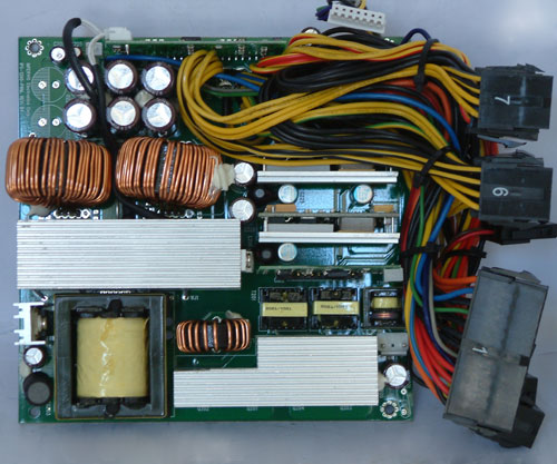
The second PCB is much more packed than the first one, carrying more components. First, we have the transformer that is responsible for the 12V rail. Then we see a couple of heatsinks, smaller transformers, coils, and Nippon Chemi-Con caps in the top. We also see another feature not many power supplies have used until now. The 3.3 and 5V rail are generated by VRMs, which can be found on the middle right side of the PCB. This may cause you to think the time has come where we won't need any of the additional rails anymore. Since modern motherboards also use VRMs to convert the voltage into whatever is needed by the components, it seems like a good time to switch to 12VDC only. A few problems remain with peripheral components like SATA drives or optical drives that still sometimes use a voltage other than 12V, but these don't need much of the other voltages.


20 Comments
View All Comments
thebackwash - Tuesday, July 8, 2008 - link
At what point does the house's wiring really begin to be a factor in sustaining the power draw? I know you're measuring watts vs. volts, but if someone could give a practical range and a better explanation as to the practical problems with running appliances with a high current draw. Volts being constant generally in a house, is it amperage that cannot be increased past a certain point?What I'm trying to ask, to anyone who can elucidate, is at what point does the house become the limiting factor as compared with the computer PSU?
I know that if I run the air conditioner in a room and someone sends a job to the (laser) printer plugged in in the same room, it trips the circuit breaker downstairs, and everybody gets an 'oh gosh, that was silly' out of it. When does one have to get new wiring run in the house to run their über gaming rig/cluster running department of defense simulations?
Carnildo - Tuesday, July 8, 2008 - link
> At what point does the house's wiring really begin to be a factor in sustaining the power draw?Right about here. 1200 watts at 75% efficiency means that, at full load, this PSU is drawing 1600 watts from the outlet. Most 120v house wiring is limited to 1800 watts (15 amps) per circuit, so if this thing is sharing an outlet with almost anything (say, a laser printer), you'll be blowing fuses on a regular basis.
If your power is only 110v (common enough), then 1200 watts at ~73% efficiency is 1650 watts at the outlet, exactly the limit of what a 15-amp circuit can provide.
thebackwash - Tuesday, July 8, 2008 - link
"Is it amperage…"I should say, "Is it amperage and the correlated wattage that can't be increased beyond a certain rating?" What's generally the bottleneck or are the two tightly linked phenomena when it comes to encountering real world engineering limitations?
JarredWalton - Tuesday, July 8, 2008 - link
If you're running 115VAC (i.e. in the US), then you need to look at the circuit that's tripping. It's probably a 15A circuit, which means that you can only run around 1700W worth of equipment on that circuit before you have the problems you describe. (115V * 15A = 1725W) The question is then how much power the various devices use.I wouldn't be at all surprised if your AC unit can pull upwards of 750W... and if it's a powerful model it could easily reach the 1250W and higher range. (Yup, AC is expensive!) A laser printer might use anywhere from 100W to 300W I suppose. I'd suggest getting something like a cheap Kill-A-Watt device and plugging the various power users into it.
Also, don't forget that lights use power as well. That 60W light bulb uses 60W, so if you have a light fixture with three bulbs, there's another 180W (or 225W if you use 75W bulbs). I highly recommend the florescent bulbs as a power efficient alternative.
gameman733 - Tuesday, July 8, 2008 - link
I think theres an error in this graph. http://images.anandtech.com/reviews/psu/2008/silve...">http://images.anandtech.com/reviews/psu/2008/silve... (DC output at 12V, look at the left side, 12.12, 12.00, 11.88, 11.94, 11.40, out of order)JonnyDough - Monday, July 7, 2008 - link
The real problem with PSUs like this is that sometimes people that are well off and on their first build who want "the best" run out and buy something like this and absolutely do not need it. It just ends up wasting electricity, which we all know is largely derived from strip-mining/coal burning which is horrible for the ozone and natural habitats.serchaing - Monday, July 7, 2008 - link
This is actually a myth, one that I also thought to be true until recently. For example, a PC that requires 340W to operate will use 340W whether the power supply is a 450W or 600W. PC Power and Cooling's web site dispels this several other PSU myths here:http://www.pcpower.com/technology/myths/#m1">http://www.pcpower.com/technology/myths/#m1
C'DaleRider - Tuesday, July 8, 2008 - link
Not the PCP&C myths again. While one or two are actually correct, the modular cable "myth" they dispel has been proven, time and again by independent testing, to be just marketing fluff by PCP&C. Add to that the "single rail is better" myth PCP&C pushes....only taken up, by the way after PCP&C absolutely failed at their design of the multi-railed Turbo Cool 1000W unit (it was horribly under powered on the rails supplied and caused problems....and their solution, instead of fixing the rails and supplying proper voltage/amperage per rail was to dump it for an easier to design single rail.)But, outside of efficiency, you are correct in that a power supply will only draw what is needed from the wall to run whatever is connected to it....no more, no less. So, a 1kW ps will only draw XA or X volts from the wall to supply what's required from it, be it 200W or 900W. It's no more expensive to run a 1200W unit, again leaving efficiency out of the equation, than a 500W unit.
And if you really look at power supplies and their construction, you'd notice that the high power units tend to be built better with better quality internals than lower wattage units.
JarredWalton - Tuesday, July 8, 2008 - link
While that is technically true, efficiency comes into play. If a PSU reaches maximum efficiency with a load of 30-70% of the rated output, then a system that requires 350W should have a 500W PSU minimum, and for optimal efficiency you almost certainly wouldn't want anything larger than 1150W (*cough*).Personally, I try to shoot for around 30 to 50% load, but even my most powerful system only draws a rather piddly 400W at peak. With a roughly 80% efficient power supply, that means the system is only using in the vicinity of 320W. Idle power draw drops to under 200W (160W or less power used by the system). This is with a quad-core Q6600 G0 stepping running at 3.40GHz, 2x2GB DDR2-800 RAM, two HDDs, and dual HD 3870 cards. It's been running quite happily with a 650W power supply for over six months.
mattclary - Monday, July 7, 2008 - link
Can anyone explain to me, or point me to the info on how it is a power supply that will be plugged into a 20 amp circuit can provide more than 20 amps?