Gigabyte GA-7ZXR (Rev. 2.2) Socket-A KT133A ATX
by Mike Andrawes on June 7, 2001 2:34 AM EST- Posted in
- Motherboards
A New Revision, A Slightly Different Look
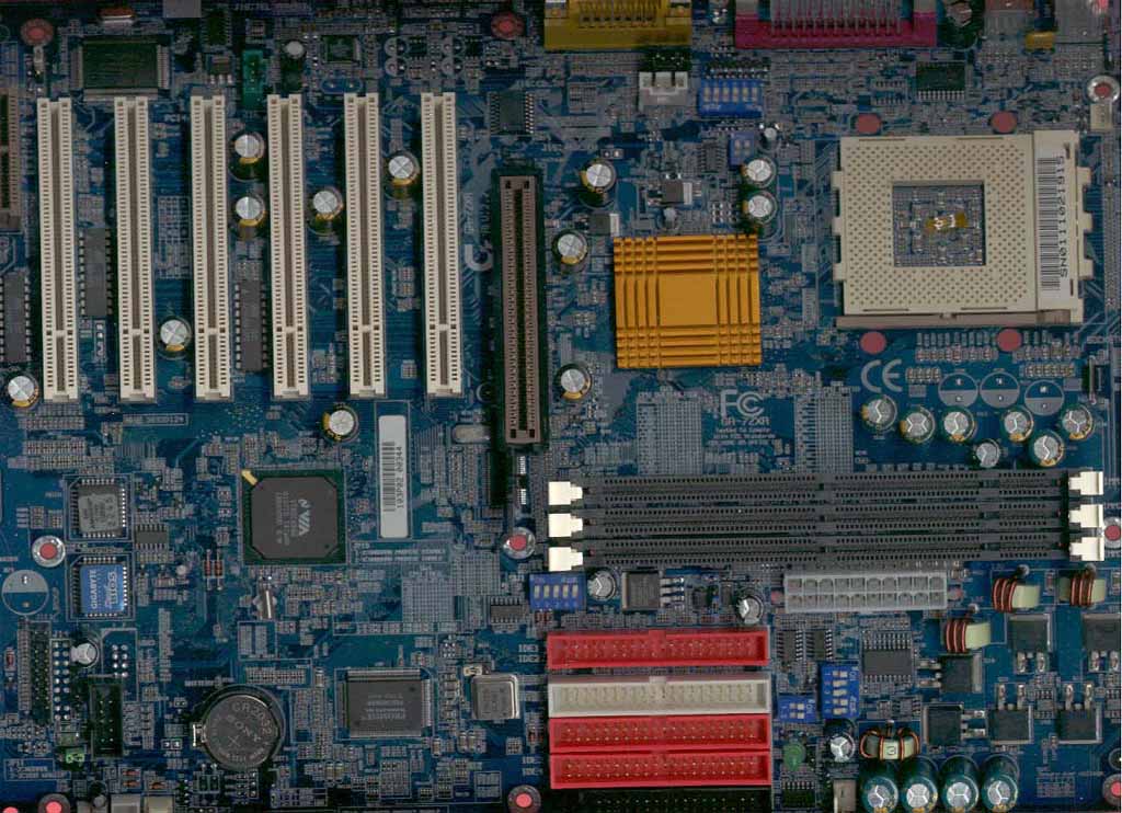
The general layout of the GA-7ZXR (2.2) is more or less the same as the original, but with a few noticeable changes. Probably the most is the removal of the ISA slot and the insertion of a sixth PCI slot. This decision is better geared for the current market since legacy ISA devices have all but disappeared by now.
The original GA-7ZXR had quite a bit of unused PCB space on the bottom right hand corner, but not this time. That space has been replaced by a more robust voltage regulator module that should allow the GA-7XR revision 2.2 to support all upcoming Socket-A processors and possibly provide improved stability to boot.
There are also several new sets of dipswitches on the new revision,, indicating the possibility that Gigabyte has inserted some new tweaking options for the hardware enthusiasts out there. We’ll get to the details in a moment.
Like the original, the power supply connector is located in front of the DIMM slot, so you will not have to worry about the power cables running over the CPU or memory. Unfortunately, the CPU socket is located quite close to the right edge of the motherboard, which makes mounting or removing a HSF unit difficult once the board is seated inside a case.
All IDE and floppy connectors are located in front of the DIMM slots. Unlike some other designs, this setup does not block the use of long PCI or AGP devices. Another thing to look out for is the size of the GA-7ZXR (2.2). It measures in at 12 by 9.5 inches, which could be a tight fit in some cases. You should make sure that your case is deep enough for the board, or the drive bays may block the IDE and floppy connectors.


0 Comments
View All Comments