ASUS CUV266 Socket-370 Apollo Pro 266 ATX
by Mike Andrawes on April 18, 2001 12:50 AM EST- Posted in
- Motherboards
A unique layout
In an attempt to improve performance and stability, ASUS sometimes comes up with a unique PCB design. A good example is the ASUS A7V and A7V133, where they introduced a vertically mounted daughterboard containing the CPU’s power regulator. The CUV266 is yet another example of this - instead of the traditional location of the DIMM slots parallel to the front edge of the board, they are now placed parallel to the right edge of the motherboard.
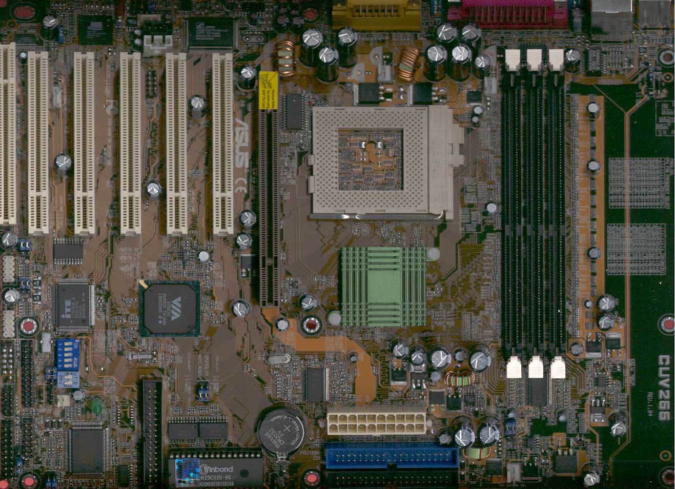
While this placement was probably chosen because it allows for shorter trace lengths between the North Bridge, CPU, and memory, it also avoids one major problem we’ve seen on a number of motherboard, where the DIMM slots are placed too close to the AGP slot, making it impossible to add or remove memory after the video card is installed. With the design of the CUV266, inserting memory is never a problem regardless of the video card’s status.
ASUS put the power supply connector in front of the North Bridge, so the power cables will not have to run over the memory or CPU, and thus it not block airflow around the CPU. They’ve also left quite a bit of space around the CPU socket, so you should have no problem installing any kind of HSF unit. Note that the memory will still have to be removed to install most HSF units.
Unfortunately, we do have a major complaint about the hefty 12 by 9.5 inch PCB. As you can see in the picture, quite a bit of space on the right side of the board is wasted. The original revision of the board had two 168-pin DIMM slots (for standard SDR SDRAM) in this space. It's not clear exactly why they were removed, but they may make a come back in a different version of the board, although we have not been able to confirm this as of now. This "wasted" space merely contributes to the manufacturing cost of the motherboard and likely could have been used more efficiently, possibly by adding another PCI slot and shifting everything to the right a bit.
The two IDE connectors are located in front of the North Bridge, so they do not block any expansion slots. On the other hand, the floppy connector is placed vertically in front of the PCI slots, but since it is located between second and third PCI slots, it shouldn’t block the use of most full-length cards in those slots. Since all front panel connectors are placed vertically along the left edge of the board, you will be able to use full-length PCI devices in all five PCI slots.


0 Comments
View All Comments