Dynamic Power Management: A Quantitative Approach
by Johan De Gelas on January 18, 2010 2:00 AM EST- Posted in
- IT Computing
How Does Power Management Work?
The BIOS settings, the power manager of the Operating System, the hardware circuits on the CPU, monitoring hardware, sensor banks... when I first started reading about power management, it quickly became very chaotic. Let's make some sense out of it.
It all starts with ACPI, the Advanced Configuration and Power Interface. In 1996, the three most influential companies in the PC world (Intel, HP, and Microsoft) together with Toshiba and Phoenix standardized power management by presenting the ACPI Specification. ACPI defines which registers a piece of hardware should have available, and what information the BIOS/firmware should offer: these are the red pieces in the graph below.
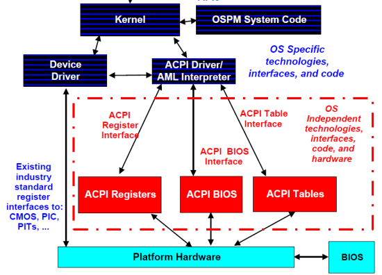
The most important information can be found in the ACPI tables, which describe the capabilities of the different devices of the platform. Once the kernel has read and interpreted them, the role of the BIOS is over. This is in sharp contrast with the power management (APM) systems that we used throughout the 80s and 90s, where for example CPU power management was completely controlled by the BIOS. The basic idea behind ACPI based power management is that unused/less used devices should be put into lower power states. You can even place the entire system in a low-power state (sleeping state) when possible. The ACPI system states are probably the best known ACPI states:
- S0 Working
- S1 processor idle and in low power state but still getting power, RAM powered
- S2 Processor in a deep sleep, RAM powered, most devices in lower power
- S3 CPU in a deep sleep, RAM still getting power, devices in the lowest power states, also known as "Standby"
- S4 RAM no longer powered, disk contains an image of the RAM contents, also known as "Hibernate"
- S5 is the soft power off
We translated the ACPI system states to their most popular implementations; the standards are actually a bit vague... or flexible if you like. You can find more details in the latest ACPI specification (revision 4.0, June 16, 2009). Windows 2008 R2, the operating system used in this article, uses the older ACPI 3.0 standard. ACPI 3.0 made it possible for different CPUs to enter a different power state.
The boss of the ACPI based power management is the power management component of the kernel. The kernel power manager handles the devices' power policy, calculates and commands the required processor power state transitions, and so on. Of course, a kernel component does not have to know every specific detail of each different device. Focusing on the CPUs, the power manager will send for example the right P-state towards a specific processor driver: in the case of Windows 2008 R2, this is either intelppm.sys or amdppm.sys. The processor driver will direct the hardware to enter the P-state requested by the kernel. This mostly happens by writing to machine specific registers, the famous MSRs. So it's clear that the CPU driver contains architecture specific code.
Processor states
There are two processor states: P-states and C-states. P-states are described as performance states; each P-state corresponds with a certain clock speed and voltage. P-states could also be called processing states: contrary to C-states, a core in a P-state is actively processing instructions.
With the exception of C0, C-states are sleep/idle states: there is no processing whatsoever. We will not go into the details as Hardware Secrets has written a very comprehensive article on C-states. We will give you a quick overview of the ACPI standard C-states, and then immediately look at the actual implementation of those C-states in modern CPUs. The ACPI standard only defines four CPU power states from C0 to C3:
- C0 is the state where the P-state transitions happen: the CPU is processing.
- C1 halts the CPU. There is no processing, but the CPU's own hardware management determines whether there will be any significant power savings. All ACPI compliant CPUs must have a C1 state.
- C2 is optional, also known as "stop clock". While most CPUs stop "a few" clock signals in C1, most clocks are stopped in C2.
- C3 is also known as "sleep", or completely stop all clocks in the CPU.
The actual result of each ACPI C-state is not defined. It depends on the power management hardware that is available on the platform and the CPU. For example, all Intel Xeons of the past years support an Enhanced C1E state, which is entered automatically if the CPU stays in C1 for a while. Modern CPUs will not only stop the clock in C3, but also move to "deeper C4/C5/C6" sleeps and drop the voltage of the CPU. The C1E, C4, C5, and C6 states are only known to the hardware; the operating system sees them as ACPI C2 or C3. We will discuss this in more detail further on in this article. Before we go into more detail on how the CPUs actually handle these C- and P-states, let's see what we assembled in our labs for testing purposes.


35 Comments
View All Comments
UrQuan3 - Thursday, January 21, 2010 - link
I'm trying to remember for 2008, but wasn't there a way to either force or suggest thread/core affinity? It looks like the scheduler was hopping all over the place on the Opterons.JarredWalton - Thursday, January 21, 2010 - link
You guys better pay attention and answer this post, or his species will try to enslave and/or wipe out the entire galaxy! ;-)mino - Wednesday, January 20, 2010 - link
I mean, not, why do you use them for this article.They are fine examples of low-power platforms, even if from vastly different markets.
But,
WHY ON EARTH DO YOU KEEP TALKING LIKE THEY WERE COMPARABLE THROUGHOUT THE ARTICLE ???
IntelUser2000 - Wednesday, January 20, 2010 - link
By the way, I don't know if you have the settings wrong or that's how it works, the Turbo Boost mode is not affected on the Home PC versions of Windows. Balanced uses Turbo Boost just as well on my Windows 7 Home Premium with Core i5 661.JarredWalton - Wednesday, January 20, 2010 - link
I was wondering this as well, but I'm not familiar with Windows Server... what I do know is that Power Saver on consumer Windows OSes really limits the CPU frequency scaling features, and it sort of looks like Balanced on the Server OS has aspects of consumer "Power Saver" as well as some elements of "Balanced". Odd to see only two power settings available, where Win7 now has at least 3 and often 5.mino - Wednesday, January 20, 2010 - link
It seems a classic example of KISS strategy of choosing the most-sensible options and so reducing decision complexity for IT people.Modes like "Max battery" have anyway no reason for existence on a server box.
RobinBee - Tuesday, January 19, 2010 - link
If you use your pc as a music server:Power saving methods ruin sound quality even if using a good sound card. The problem is »electronic« sound distortion. I do not know why this happens.
Also: The chosen number of IRQ pr. second in a net card can ruin sound quality too. Why, I do not know.
Anato - Tuesday, January 19, 2010 - link
I'm interested to see results from different operating systems which may be better at controlling processes in different CPU's. Namely no CPU hopping and is their power management as efficient as Windows is.Most interested at:
Linux and Solaris
JohanAnandtech - Tuesday, January 19, 2010 - link
Excellent suggestion :-). Problem is to keep the application the same. We currently tested SQL Server 2008 on Windows 2008 and of course this can not be done on Linux. However, I am not stranger to linux as a server.I am no fan of MySQL on Windows, but maybe this has improved. Would MySQL on Windows and Linux makes sense as a comparison?
maveric7911 - Tuesday, January 19, 2010 - link
Why not use oracle ;)