The Gigabyte GA-X48T-DQ6 - Redefining the High End?
by Rajinder Gill on January 2, 2008 3:15 AM EST- Posted in
- Motherboards
BIOS - Continued
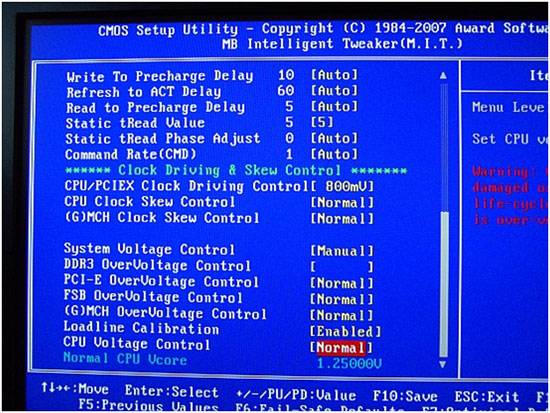
Write To Precharge Delay
Again, this setting is offset by -10. The range of interest in BIOS is between 6 and 13 (16 to 23 actual). Higher numbers mean less performance, but help with stability.
Refresh To Act Delay (aka tRFC)
48-72 is the range of interest, lower settings can have a huge impact on memory bandwidth at the expense fo stability. For benchmarking 48-55 is preferred. For stability testing at high memory speeds start high (72) and work downwards slowly.
Read to Precharge Delay (tRTP)
A setting of 4-6 is usually sufficient across the entire range of FSB and memory speeds that this board offers. 4 is tight and used for benchmarking, while a setting of 5-6 gives stability as FSB and memory speed is scaled. For high FSB speeds with quad-core processors or 4GB memory overclocking a setting of 6 may be preferable.
Static tREAD Value
This setting is more commonly known as Performance Level or tRD and is the most effective chipset performance register available for adjustment on this motherboard. As FSB and memory speed are scaled, tRD and Northbridge voltage will have to be increased to accommodate the additional data throughput. The idea when seeking outright system performance is to run the tightest tRD possible at any given FSB or memory speed. Our retail sample board maxed out at a tRD of 6 at 400 FSB using the 2:1 divider. For 65nm dual core processors, a tRD setting of 7 is usable up to 500FSB. For lower chipset voltages and stability increase tRD by +1 over these figures if stability issues are experienced.
tRD Phase Shift
The user selectable scale runs from 1-31. Setting Auto results in a selection of 0, which means both memory channels remain at the default Performance Level. tRD phase shift allows the user to run either memory channel at a lower Performance Level than the applied BIOS setting of Static tRD Delay. The scale used by Gigabyte is not really intuitive, as it does not immediately show the user which of the memory channel phases are being lowered - at any of the settings available. The number of available or effective phases varies according to the memory divider being used. The explanation of how the phases are configured is outside the scope of this review and deserves a write-up of its own. Look for an upcoming article on AnandTech that will fully describe Intel chipset overclocking in layman terms.
For now, we will stick with the basic rule that a tRD phase adjustment subtracts 1 from the static tRD level at a given point in the FSB/memory read transfer cycle. This function only needs to be used (experimented with) when using FSB speeds that fall between two Performance Level (tRD) FSB limits. Every increase in Performance Level requires a suitable rise in FSB speed to make up the associated memory access latency and bandwidth deficit. If a small hike past a Performance Level limit at a given FSB is made (for additional processor speed), valuable access latency and memory bandwidth is lost unless the rise in FSB speed is very substantial.
With the FSB limits of quad-core processors falling below 470FSB and requiring a tRD of 7-8 in most cases, it can be far easier both in terms of BIOS tuning and board voltages to retain a low tRD of 5 or 6 at around 400FSB using a higher CPU multiplier. The gray area in terms of performance falls between 420-450FSB, where a tRD of 6 starts requiring very high levels of Northbridge voltage to hold steady. When benchmarking with a motherboard there may be instances (due to chipset limitations) where running these intermediate FSBs is the only option. In this instance, it makes sense to apply tRD phase shifts in an attempt to minimize chipset latency loss.
We look at the memory bandwidth and access latency changes at all 31 steps of tRead Phase Adjust below. Please note, the table is for demonstration purposes only; actual board abilities and maximum operating conditions may differ according to a number of variables. We expect that users with quad-core processors will use the 1:2 memory divider at all times, to maximize memory bandwidth at the FSB levels that are available to them. Dual-core CPUs have access to higher stable FSB speeds, in which case using one of the lower dividers to peg memory speed to acceptable and operable speeds will be required.
 |
The rows highlighted in the darker blue represent the most aggressive Phase Adjust points. The table above shows that using the 1:2 memory divider, tRD Phase Adjust settings of 3, 7, 11, 15, 19, 23 (non boot), 27 (non boot), and 30 (non boot) are the most aggressive. In fact, these settings draw an almost complete parallel to running a tRD of 6. To increase FSB potential, some of the less aggressive phase shift settings will need to be used. Again, we stress that most users will not find much to gain in these adjustments. However, for those who are truly passionate about performance tweaking, tRD phase adjustments represent a method of almost linear memory bandwidth and latency scaling throughout the range of chipset capability with a particular CPU. These kinds of tweaks generally bear interest to those who benchmark for maximum scoring potential. Retaining chipset latency can be the difference between a record and tenth place, as there is little to separate overall processor speeds at the top of the Futuremark Orb these days.
We were intrigued by the fact that tRD Phase Shift settings of 23, 27, and 30 would not boot even if we changed Northbridge straps. We managed to get a peek at just how aggressive the non-booting registers were. The Northbridge was set to the 1333 chipset strap with the 1:2 memory divider ratio and 1N command rate at a tRD of 8. We then set a tRD phase shift setting to 23, 27 or 30 and proceeded to boot into Windows. Once Windows had booted up, we lowered the tRD back down to 7 via Memset. The interesting fact is that the board was fully capable of running the Prime95 Torture test at these points for significant periods of time. This points the finger at an inadequate BIOS, rather than a chipset limitation. What is also interesting is that the registers of 23 and 27 are actually more aggressive than running a flat tRD of 6. This implies that these registers may be cross-linked to other hidden chipset performance enhancing registers.


37 Comments
View All Comments
Ozlaw - Monday, June 23, 2008 - link
I recently switched the inner workings of my computer from a Sriker Extreme, X8000 CPU and an 8800 GTX, to the Gigabyte GA-EX38T-DQ6, with an Asus HD 3870 X2 1gb (and I was about to add another in crossfireX, until I found out AMD was rolling out the 4000's series X2 early, actually possibly in Q3 of this year). If I had known, which is the story of my life and computers, that a newer chipset was coming out so soon, I would have waited for the 48T. The funny thing is that ever since I studied coomputer progaramming in college in the 70's, and began building my own computers when costs became parctical to do so, I suscribe to all the industry news but always miss something big.Oh well I can say that the 38T, since it was designed aroung quad core, including the extremes, instead of relying on BIOS updates to recoginize and work with critical hardware, such as the 680i in my old Striker Extreme was doing (I had the QX6850 in int for a time)in and of itself made an ennourmous difference in my computer's speed and functionality.
THanks for a good article and now I am going to have to decide whether to buy a new motherboard when I buy the new graphics cards as I admit to being on of those weak early consumers of tech products, althhough I am getting better when it comes to Intel's cpu's now that they have become a CPU of the month club.
papatsonis - Wednesday, April 16, 2008 - link
"(G)MCH Overvoltage ControlDefault voltage is 1.45V, and the available voltage scale provides an overvoltage of 0.025-0.775V. There an actual undervoltage of 0.2V from the BIOS set overvoltage. For example, as the stock voltage is set to 1.45V a BIOS setting of +0.50V would imply a voltage of 1.95V. However setting +0.50V gives an actual voltage of 1.75V, suggesting an undervoltage of 0.2V. "
The default voltage of X38/X48 is 1.25v (and in the article explaining tRD values , states that also) , the gigabyte in fact OVERvoltages MCH , when set to normal , to 1.45volt , but when adjusting values, it sets correct values (multimetered) e.g. +0.125 ->~ 1.38v
Galvin - Monday, April 28, 2008 - link
I dont have a volt meter. But I did verify thats what happening.I have the x48 ddr2 version. Normally the NB heatsink is too hot to keep my fingers on it. So if you run less voltage the heatsink should be cooler to the touch. Which is what happened. I set the overvolt for the MCH to 0.025 then rebooted. Waited a few min and I was able to hold my fingers to the heatsink without burning. I did this 2 more times to be sure.
Surprised no one has found this before. That explains why the NB heatsink was crazy hot.
Thanks
neat1 - Sunday, January 6, 2008 - link
http://www.firingsquad.com/hardware/intel_skulltra...">http://www.firingsquad.com/hardware/intel_skulltra...neat1 - Sunday, January 6, 2008 - link
Does this board supp sli or is there still only crossfire support on the x48 chipset? (which would be kind of odd)Looking fwd 2 see the ASUS X48 tested
Regard/neat1
Rajinder Gill - Sunday, January 6, 2008 - link
Hi,Right now Nvidia has no plans whatsoever to allow SLI on the desktop Intel chipssets. Skulltrail may be the only exception to this. Of course, that's assuming Skulltrail ever gets released.
regards
Raja
Rob94hawk - Sunday, January 6, 2008 - link
Benchmarks with skulltrail or just hype?Rajinder Gill - Sunday, January 6, 2008 - link
Hi Rob,Personally I have not seen anything of Skulltrail myself, Intel are notably tight-lipped about publishing anything. Of course we'd all love to have a play...lol
regards
Raja
kilkennycat - Friday, January 4, 2008 - link
Is Gigabyte paying Anandtech for front-cover "pseudo-advertising"? I though Anandtech exclusively reviewed quality products. Seems as if the pre-fitering within Anandtech of products for review needs to be strengthened.This review is so full of wishful thinking about future BIOS updates (whhich may never materialize) that I want to scream. Surely there are computer-related products in a far more mature state begging for serious technical reviews?
Rajinder Gill - Friday, January 4, 2008 - link
At least the preview/review let's people know what to expect at present. I guess I am wishful, because I hate to see good products go to waste via an inadequate BIOS. Immediate maturity with top-end performance boards (the reviews I concentrate on) is hard to find, almost impossible in fact. Occasionally we find a gem, when we do, we write about it. Not every board that comes down the channel is going to make the masses happy, especially in this segment. It's one of the toughest segments of all, the budget minded will never be happy with it. But then these products are not aimed at the budget segment at all. In the PC world there's no such thing as linear performance scaling per dollar. This board needed a 2 stage review, because fo the length of time the cascade cooled results can take. Where this may not be the typical approach, the performance boards are used by a percentage of this crowd. The rest is the more stable down to earth stuff which we endeavour to cover with the BIOS guides. It just so happens this all fell in with the Christmas season, when most companies go into shutdown.We review these boards in a way that the people who have the dollar or inclination to spend this kind of money will use them, no more, no less.
regards
Raja