ASUS P5NSLI: Core 2 Duo and SLI on a Budget
by Gary Key on August 22, 2006 5:30 AM EST- Posted in
- Motherboards
ASUS P5NSLI: Features
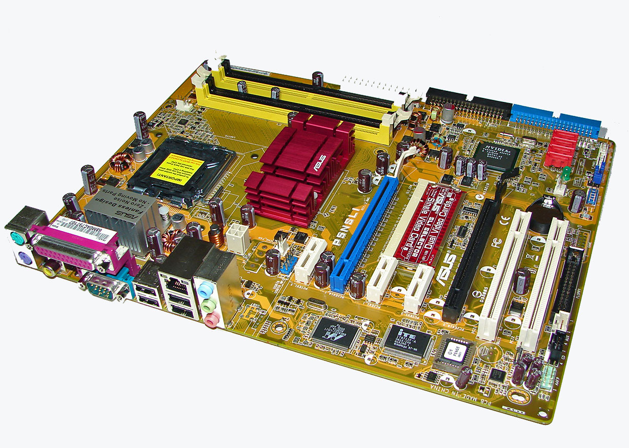
ASUS designed an extremely well laid out board with all major connections easily reached. The ASUS layout provides very good clearance for cards and components while being simple to install in a mid-size ATX case. The board features a 3-phase voltage regulator power design that provided very good stability during general usage and overclocking.
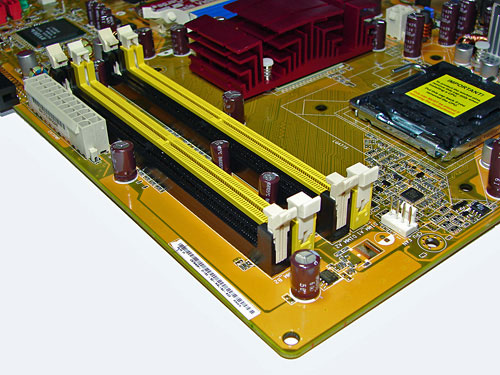
The DIMM module slots' color coordination is correct for dual channel setup. The memory modules are slightly difficult to install with a full size video card placed in the first PCI Express X16 slot. The 24-pin ATX connector is conveniently located on the edge of the board in front of the number four DIMM slot. The CPU fan header is located at the edge of the number one DIMM slot and due to the distance from the CPU it requires your heatsink/fan to be properly oriented if the cable is short.
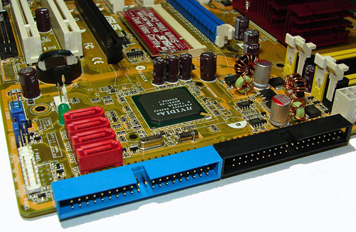
The red NVIDIA 570SLI SATA ports are conveniently located on the board's edge and in front of the blue IDE port connector. Unlike other recently reviewed boards the SATA ports are not color coded for primary and secondary operation, though that is a minor concern. We found the positioning of the SATA ports to be excellent when utilizing the PCI slots, primary IDE port connector, or the second X16 PCI Express slot. The NVIDIA MCP51 chipset does not require a heatsink for cooling.
The blue primary and black secondary NVIDIA 570SLI IDE port connectors are located on the edge of the board and did not present any connection issues in our mid-size ATX case. The location of this connector is very good for most cases and those users still utilizing IDE hard drives. The chassis panel, CMOS jumper block, and fan header is located on the left edge of the board. The clear CMOS jumper block is a traditional jumper design and is easily accessed.
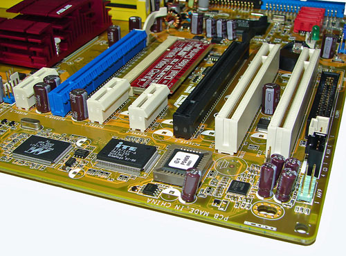
The board comes with two physical PCI Express X16 connectors, three PCI Express X1 connectors, and two PCI 2.3 compliant 32-bit connectors. The layout of this design offers an exceptional balance of expansion slots for a mainstream board.
The first PCI Express X1 connector is located to the right of the second chassis fan header, above the primary X16 slot. The location of this PCI Express X1 connector allows installation of most peripheral PCI Express cards and is not blocked by most video card designs.
The first physical X16 connector (blue) is located next and is followed by the second and third PCI Express X1 connectors. When utilizing a dual slot video card the second PCI Express X1 connector will be physically rendered useless. We did not have any issues utilizing this slot with video cards containing single slot cooling systems.
The second physical X16 connector (black) is located next and is followed by the two PCI 2.3 compliant 32-bit connectors. When utilizing a dual slot video card the first PCI connector will be physically rendered useless. Again, we did not have any issues using this slot with cards containing single slot cooling systems.
The SLI paddle card is located behind the two PCI Express X1 slots and must be installed properly for SLI or multiple GPU installations. The black floppy drive connector is located in an inconvenient position next to the last PCI slot.
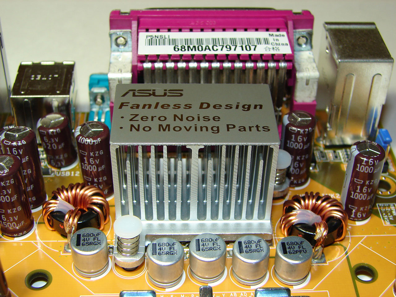
Returning to the CPU socket area, we find an ample amount of room for alternative cooling solutions. We utilized the stock Intel heat sink but also verified several aftermarket cooling systems such as the Thermaltake Big Typhoon, Zalman CNPS 9500, Tuniq 120 Tower, and our Scythe Infinity would fit in this area during our tests. However, due to the SPP heatsink size the installation of larger air or water-cooling solutions could be problematic.
The NVIDIA nForce 570SLI SPP chipset is passively cooled with a large heatsink unit that did not interfere with any installed peripherals. Our only concern is the heat generated by the SPP causes the heatsink to reach temperatures that can burn your fingers after extended use. While the system remained very stable we would highly suggest a cooling solution for this area.
ASUS places the four-pin ATX power connector at the top of the CPU socket area and near the SPP heatsink. This connector is located in a difficult position and can hamper airflow with cabling that crosses over directly over the CPU heatsink/fan. During our testing with the Zalman CNPS 9500 we had to bend our 4-pin connector and run the cable around the heatsink fins in order to connect it. This is our lone issue with the general layout and usage of peripherals on this board.
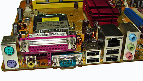
The PS/2 mouse and keyboard ports are located to the far left of the I/O panel. The serial port (COM1) is located to the left of the USB ports and below the LPT parallel port. The S/PDIF coaxial out connector is located to the right of PS2 ports. The LAN (RJ-45) port and the second pair of USB 2.0 connectors are located next to the first set of USB ports. The LAN (RJ-45) port has two LED indicators representing Activity and Speed of the connection. The audio panel consists of three ports that can be configured for 2, 4, and 6-channel audio connections.
 |
| Click to enlarge |
ASUS designed an extremely well laid out board with all major connections easily reached. The ASUS layout provides very good clearance for cards and components while being simple to install in a mid-size ATX case. The board features a 3-phase voltage regulator power design that provided very good stability during general usage and overclocking.
The DIMM module slots' color coordination is correct for dual channel setup. The memory modules are slightly difficult to install with a full size video card placed in the first PCI Express X16 slot. The 24-pin ATX connector is conveniently located on the edge of the board in front of the number four DIMM slot. The CPU fan header is located at the edge of the number one DIMM slot and due to the distance from the CPU it requires your heatsink/fan to be properly oriented if the cable is short.
The red NVIDIA 570SLI SATA ports are conveniently located on the board's edge and in front of the blue IDE port connector. Unlike other recently reviewed boards the SATA ports are not color coded for primary and secondary operation, though that is a minor concern. We found the positioning of the SATA ports to be excellent when utilizing the PCI slots, primary IDE port connector, or the second X16 PCI Express slot. The NVIDIA MCP51 chipset does not require a heatsink for cooling.
The blue primary and black secondary NVIDIA 570SLI IDE port connectors are located on the edge of the board and did not present any connection issues in our mid-size ATX case. The location of this connector is very good for most cases and those users still utilizing IDE hard drives. The chassis panel, CMOS jumper block, and fan header is located on the left edge of the board. The clear CMOS jumper block is a traditional jumper design and is easily accessed.
The board comes with two physical PCI Express X16 connectors, three PCI Express X1 connectors, and two PCI 2.3 compliant 32-bit connectors. The layout of this design offers an exceptional balance of expansion slots for a mainstream board.
The first PCI Express X1 connector is located to the right of the second chassis fan header, above the primary X16 slot. The location of this PCI Express X1 connector allows installation of most peripheral PCI Express cards and is not blocked by most video card designs.
The first physical X16 connector (blue) is located next and is followed by the second and third PCI Express X1 connectors. When utilizing a dual slot video card the second PCI Express X1 connector will be physically rendered useless. We did not have any issues utilizing this slot with video cards containing single slot cooling systems.
The second physical X16 connector (black) is located next and is followed by the two PCI 2.3 compliant 32-bit connectors. When utilizing a dual slot video card the first PCI connector will be physically rendered useless. Again, we did not have any issues using this slot with cards containing single slot cooling systems.
The SLI paddle card is located behind the two PCI Express X1 slots and must be installed properly for SLI or multiple GPU installations. The black floppy drive connector is located in an inconvenient position next to the last PCI slot.
 |
| Click to enlarge |
Returning to the CPU socket area, we find an ample amount of room for alternative cooling solutions. We utilized the stock Intel heat sink but also verified several aftermarket cooling systems such as the Thermaltake Big Typhoon, Zalman CNPS 9500, Tuniq 120 Tower, and our Scythe Infinity would fit in this area during our tests. However, due to the SPP heatsink size the installation of larger air or water-cooling solutions could be problematic.
The NVIDIA nForce 570SLI SPP chipset is passively cooled with a large heatsink unit that did not interfere with any installed peripherals. Our only concern is the heat generated by the SPP causes the heatsink to reach temperatures that can burn your fingers after extended use. While the system remained very stable we would highly suggest a cooling solution for this area.
ASUS places the four-pin ATX power connector at the top of the CPU socket area and near the SPP heatsink. This connector is located in a difficult position and can hamper airflow with cabling that crosses over directly over the CPU heatsink/fan. During our testing with the Zalman CNPS 9500 we had to bend our 4-pin connector and run the cable around the heatsink fins in order to connect it. This is our lone issue with the general layout and usage of peripherals on this board.
The PS/2 mouse and keyboard ports are located to the far left of the I/O panel. The serial port (COM1) is located to the left of the USB ports and below the LPT parallel port. The S/PDIF coaxial out connector is located to the right of PS2 ports. The LAN (RJ-45) port and the second pair of USB 2.0 connectors are located next to the first set of USB ports. The LAN (RJ-45) port has two LED indicators representing Activity and Speed of the connection. The audio panel consists of three ports that can be configured for 2, 4, and 6-channel audio connections.


27 Comments
View All Comments
techkn0w - Tuesday, September 4, 2007 - link
I just got back my mobo from Asus RMA (I sent it in due to memory errors) and it's still giving memory errors. This just sucks and I read some websites that many users are getting errors too. Just thought I should put it out here so you guys know. Ok, back to checking the Asus forums.redpriest_ - Tuesday, August 22, 2006 - link
You mention the 590 SLI chipset, can we get a comparison versus that too?Gary Key - Tuesday, August 22, 2006 - link
The 590SLI Intel is under NDA currently. The 590SLI production boards will be different than the reference board we previewed earlier.
Napyan - Tuesday, August 22, 2006 - link
Sorry, kind of an idiot question but I've read the article 3 times now trying to figure it out. If the board doesn't support DDR2-800 how was it tested on it? Overclocking?Gary Key - Wednesday, August 23, 2006 - link
The chipset officially supports DDR2-533/667 although it will "unofficially" support DDR2-800 if bios support is provided by the supplier. Anything about DDR2-800 is overclocking and to a certain extent so is DDR2-800 although it is a very gray area. I apologize as this statement was in my original text and I removed it during the edit process. I will update the article.
Gary Key - Wednesday, August 23, 2006 - link
Where is the edit button? Anything above DDR2-800......Napyan - Wednesday, August 23, 2006 - link
Thank you for clearing that up for me.JarredWalton - Tuesday, August 22, 2006 - link
It does support DDR2-800. The problem is that it becomes wonderfully unstable if you push things too hard, i.e. 3-3-3 timings.JarredWalton - Tuesday, August 22, 2006 - link
Soon - as soon as we get it.yacoub - Tuesday, August 22, 2006 - link
Funny how your original look at NForce5 (as linked on page 2 of this article) showed 570 was supposed to also include DualNet, yet this board does not. :[