The MSI MEG X399 Creation Motherboard Review: The New 16-Phase Shark In Town
by Gavin Bonshor on August 13, 2018 8:59 AM EST- Posted in
- Motherboards
- Gaming
- AMD
- MSI
- Overclocking
- ThreadRipper
- X399
- TR4
- Threadripper 2
System Performance
Not all motherboards are created equal. On the face of it, they should all perform the same and differ only in the functionality they provide - however, this is not the case. The obvious pointers are power consumption, but also the ability for the manufacturer to optimize USB speed, audio quality (based on audio codec), POST time and latency. This can come down to the manufacturing process and prowess, so these are tested.
Power Consumption
Power consumption was tested on the system while in a single ASUS GTX 980 GPU configuration with a wall meter connected to the Thermaltake 1200W power supply. This power supply has ~75% efficiency > 50W, and 90%+ efficiency at 250W, suitable for both idle and multi-GPU loading. This method of power reading allows us to compare the power management of the UEFI and the board to supply components with power under load, and includes typical PSU losses due to efficiency. These are the real world values that consumers may expect from a typical system (minus the monitor) using this motherboard.
While this method for power measurement may not be ideal, and you feel these numbers are not representative due to the high wattage power supply being used (we use the same PSU to remain consistent over a series of reviews, and the fact that some boards on our test bed get tested with three or four high powered GPUs), the important point to take away is the relationship between the numbers. These boards are all under the same conditions, and thus the differences between them should be easy to spot.
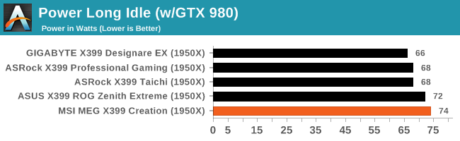
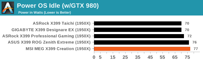
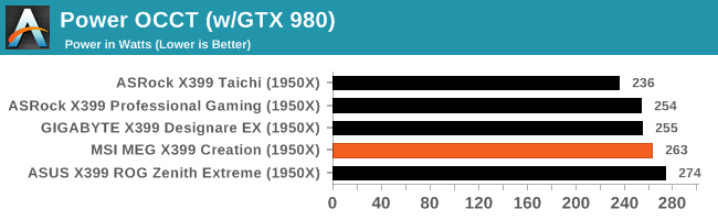
Aside from the other four boards being tested, the only major differences in specification are the graphics card and power supply used. In OCCT, the only variations are in the idle power draw of the components, but it's still a good indication of where power consumption should be. The MSI X399 Creation in a long idle and idle state pull slightly more watts at the wall than the other boards on test, but at full loud under OCCT, the power draw falls below that of the ASUS X399 ROG Zenith Extreme; a board on the same level specifications, feature and price wise.
Non-UEFI POST Time
Different motherboards have different POST sequences before an operating system is initialized. A lot of this is dependent on the board itself, and POST boot time is determined by the controllers on board (and the sequence of how those extras are organized). As part of our testing, we look at the POST Boot Time using a stopwatch. This is the time from pressing the ON button on the computer to when Windows starts loading. (We discount Windows loading as it is highly variable given Windows specific features.)
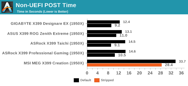
While the boot times of the other boards on test seem very quick indeed, the MSI MEG X399 Creation displayed some very long and dreary POST times. In a stripped state with controllers such as LAN, onboard audio and other disableable controllers turned off, POST times did improve but still come in more than double than the next slowest board. This could quite possibly be an anomaly, but as more X399 boards come in, I will re-test to see if it's a consistent issue with the test set-up, although nothing else seems amiss.
DPC Latency
Deferred Procedure Call latency is a way in which Windows handles interrupt servicing. In order to wait for a processor to acknowledge the request, the system will queue all interrupt requests by priority. Critical interrupts will be handled as soon as possible, whereas lesser priority requests such as audio will be further down the line. If the audio device requires data, it will have to wait until the request is processed before the buffer is filled.
If the device drivers of higher priority components in a system are poorly implemented, this can cause delays in request scheduling and process time. This can lead to an empty audio buffer and characteristic audible pauses, pops and clicks. The DPC latency checker measures how much time is taken processing DPCs from driver invocation. The lower the value will result in better audio transfer at smaller buffer sizes. Results are measured in microseconds.
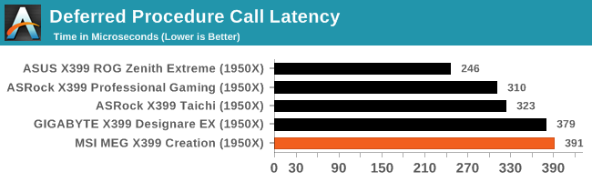
None of the boards tested has been optimized for DPC latency, and as it stands, the MSI MEG X399 Creation has posted the worst score so far. This is even though all of the tested offerings on the X399 chipset have been somewhat higher than usual as well.


17 Comments
View All Comments
Chaitanya - Monday, August 13, 2018 - link
Even on high end there are no proper heatsinks for vrms its that silly solid chunks of aluminium with minimal fin stack that dominates. It was refreshing to see Gigabyte go back to old school finned heatsinks for their X470 board.Questor - Monday, August 13, 2018 - link
Flash over substance. It's a pitiful way to make a product.Oxford Guy - Wednesday, August 15, 2018 - link
Not to mention it looks worse than aluminum or copper fins.Oxford Guy - Wednesday, August 15, 2018 - link
ASUS and Gigabyte released VRM coolers back in 2013 that would be used with water systems as well as air (hybrids). This was for quad core non-prosumer CPUs, too. But, we have certainly progressed as an industry. Now, we can have really cool paint and LEDs instead of efficient VRM cooling.Questor - Monday, August 13, 2018 - link
Hopefully Buildzoid will get a hold of this model motherboard and verify it is what MSI says it is. I'm so tired of marketing lying about computer components, I don't believe much of what I read from the makers. Thus I am in "prove it" mode. Unfortunately, most reviewers either don't look or don't know what they see if they do.Ian Cutress - Monday, August 13, 2018 - link
This is one of the reasons we have our power delivery component table in our reviews now. Gavin knows what he's talking about - he did a good deconstruction of the B450 boards that exhibit the behaviour you are describing.https://www.anandtech.com/show/13085/the-asrock-b4...
Gothmoth - Monday, August 13, 2018 - link
it´s an 8 phase. as 2 "phases" are always in phase and therfore can not count as two seperate phases.one is marekting the other is reality.
diehardmacfan - Monday, August 13, 2018 - link
mmm no this looks like an actual 16 phase, just a "dumb" 16 phase because of the doublers.the cooling looks pretty crappy though.
KateH - Sunday, August 19, 2018 - link
i looked up the datasheet for the doublers mentioned and it describes them as outputting 2 PWM signals 180* apart so functionally its rectifying 16 phases, but the regulator sees 8.KateH - Sunday, August 19, 2018 - link
the datasheet if anyone is interested:https://www.infineon.com/dgdl/ir3599.pdf?fileId=55...
neat trick, and according to the sheet the doublers can also function as quadruplers so if one wanted 32 phases for some insane reason they could do that with the 8-channel controllers