Overclocking Intel's New 45nm QX9650: The Rules Have Changed
by Kris Boughton on December 19, 2007 2:00 AM EST- Posted in
- CPUs
Testing System Stability with Prime95
For over 10 years a site operated by a group called the Great Internet Mersenne Prime Search (GIMPS) has sponsored one of the oldest and longest-running distributed computer projects. A Mersenne prime is a prime of the form 2P-1 where "P" is a prime number (an integer greater than one is called a prime number if its only divisors are one and itself). At this time there are only 44 known Mersenne primes. The simple client program, called Prime95, originally released and made available for public download in early January 1996, allows users interested in participating in the search for other Mersenne primes the opportunity to donate spare CPU cycles to the cause. Although few overclockers participate in GIMPS, many use Prime95 for testing overall system stability. While there are other programs available for download designed specifically for this reason, few can match the ease of use and clean interface provided by Prime95.
The load placed on the processor is quite intense (nominally 100% on each core, as reported by Windows) and if there are any weaknesses in the system Prime95 will quickly find them and alert the user. Additionally, newer versions of the program automatically detect the system's processor core count and run the appropriate number of threads (one per core), ensuring maximum system load with the need for little to no user input. It is important to note that high system loads can stress the power supply unit (PSU), motherboard power circuit components, and other auxiliary power delivery systems. Ultimately, the user is accountable for observing responsible testing practices at all times.
Failures can range from simple rounding errors and system locks to the more serious complete system shutdown/reset. As with most testing the key to success comes in understanding what each different failure type means and how to adjust the incorrect setting(s) properly. Because Prime95 tests both the memory subsystem and processor simultaneously, it's not always clear which component is causing the error without first developing a proper testing methodology. Although you may be tempted to immediately begin hunting for your CPU's maximum stable frequency, it's better to save this for later. First efforts should focus on learning the limits of your particular motherboard's memory subsystem. Ignoring this recommendation can lead to situations in which a system's instability is attributed to errors in the wrong component (i.e., the CPU instead of the MCH or RAM).
To begin, we first start by identifying personal limits regarding measurable system parameters. By bounding the range of acceptable values, we protect ourselves from needless component damage - or even worse, complete failure. We have listed below the parameters we consider critical when overclocking any system. In most cases, monitoring and limiting these values will help to ensure trouble-free testing.
Overall System Power Consumption: This is the system's total power draw as measured from the wall. As such, this is the power usage sum of all components as well as power used by the PSU in converting household AC supply current to the DC rails used by the system. P3 International makes a wonderful and inexpensive product called the Kill-A-Watt that can monitor your system's instantaneous power draw (Watts), volts-amps (VA) input, PSU input voltage (V), PSU input current (A), and kW-hr power usage.
A conservative efficiency factor of about 80% works for most of today's high-quality PSUs - meaning that 20% of the total system power consumption goes to power conversion losses in the PSU alone. (Although absolute PSU efficiency is a function of load, we estimate this value here as a single rating for the sake of simplicity.) Knowing this we can estimate how much power the system is really using and how much is nothing more that heat dissipated by the power supply. For example, if your system draws 300W under load then 240W (0.8 x 300W) is the load on the output of the PSU and the remaining 60W (300W - 240W) leaves the PSU as heat. It is important to note that manufacturers rate PSUs based on their power delivery capabilities (output) and not their maximum input power.
Using what we have learned so far, we can calculate the maximum allowable wall power draw for any PSU. Consider the case of a high-quality 600W unit with a conservative efficiency rating of 80%. First find 90% of the maximum output rating (0.9 x 600W = 540W) - this allows us to limit ourselves to at least a small margin below our PSU's maximum load. Now divided that by 0.8: 540W / 0.8 = 675W. For a good 600W PSU we feel comfortable in limiting ourselves to a maximum sustained wall power draw of about 675W as read by our Kill-A-Watt. (Should you decide to use a lower quality power supply, you will get lower efficiency and you won't want to load the PSU as much. So, 70% efficiency and a maximum load of 75% of the rated 600W would yield 643W… only your components are getting far less actual power and the PSU needs to expel a lot more heat. That's why most overclockers value a good PSU.)
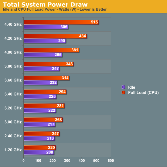
Our PSU's total power draw as a function of CPU speed (full load)
Keep in mind that the power consumption values based on CPU testing alone will not be representative of total system load when running graphics intensive loads, like 3D gaming. The GPU(s) also contribute significantly to this value. Be sure to account for this when establishing your upper power consumption limit. Alternatively, buy a more powerful PSU as overstressing one is a great way to cause a failure.
Processor Voltage (Vcore) and Core Temperatures: As process technology node sizes decrease, so do maximum recommended Vcore values. Better cooling can sometimes allow for higher values but only to the extent that temperatures remain manageable. Even with high-end water-cooling, CPU voltages in excess of ~1.42V with 45nm quad-cores result in extremely elevated full-load core temperatures, especially when pushing above 4.2GHz or higher. Those using traditional air-cooling will more than likely find their limits somewhere around 1.36V or even lower.
Intel's Core 2 family of processors is incredibly resilient in the face of abuse when it comes to Vcore values greater than the maximum specification - damaging your CPU from excessive core voltage will be difficult. In some cases, heat will be the limiting factor. We'll go into more detail later in the article when we discuss the effect of frequency and voltage scaling on maximum sustained core temperatures.
Memory Voltage (VDimm): Unlike CPUs, current memory modules are extremely sensitive to overvoltage conditions and may begin to exhibit early signs of premature failure after relatively short periods of abuse. Most high-performance memory manufactures go to great lengths testing their products to maximum warranted voltages. Our recommendation, which never changes, is that you observe these specifications at all times. For those dealing with conservatively rated memory the following are goods rules of thumb when it comes to memory voltage: 2.4V maximum for DDR2 and 2.1V maximum for DDR3. Exceeding these voltages will more than likely accelerate degradation. Subjecting memory to voltages well in excess of these values has caused almost immediate failure. Remember, just because your motherboard BIOS offers ridiculously high memory voltages doesn't mean you need to test them out.
Northbridge Voltage (Vmch): The Memory Controller Hub (MCH), sometimes referred to as the Northbridge, is responsible for routing all I/O signals and data external to the CPU. Interfaced systems include the memory via the Front Side Bus (FSB), graphics card(s) over PCI Express, and the Southbridge using a relatively low-bandwidth DMI interface. Portions of the MCH run 1:1, 2:1 and even 4:1 with the Front Side Bus (FSB) meaning that just like CPU overclocking, raising the FSB places an increased demand on the MCH silicon.
Sustained MCH voltages in excess of about 1.7V (for X38) will surely cause early motherboard failures. Because Intel uses 90nm process technology for X38, we find that voltages higher than those applied to 65/45nm CPUs are generally fine. During the course of our X38 testing we found the chipset able to drive two DIMM banks (2x1GB) at 400MHz FSB at default voltage (1.25V) while four banks (4x1GB) required a rather substantial increase to 1.45V. Besides FSB and DIMM bank population levels, a couple of other settings which significantly influence minimum required MCH voltages are Static Read Control Delay (tRD) - often called Performance Level - Command Rate selection (1N versus 2N), and the use of non-integer FSB:DIMM clocking ratios. Our recommendation is to keep this value below about 1.6V when finding your maximum overclock.


56 Comments
View All Comments
mariedeguzman - Friday, June 19, 2009 - link
Thanks for this post, this is a great article and a good help to those who need advices about this post.Markfw900 - Thursday, January 10, 2008 - link
My Gigabyte P35-DQ6 does have what you say is voffset, but is has NO vdroop from idle to load. I believe this is because it has a far superior power delivery system. I don't have an instrument to tell me any differences that may happen in nano-seconds on the voltage, but overall, it never seems to change. This would be consistant with a high quality board. So why do you say its a feature ? I can see how a mfg may undervolt to not go over recommended vcore for non-overclocked cpu's, but if I didn't overclock, my board wouldn't have vdroop either.Its just cheap motherboards, not a "feature". If I am wrong, please test a DQ6 and show the results.
LaGUNaMAN - Saturday, January 5, 2008 - link
One of the best tech articles I've read in awhile. (^^,)isvaljek - Tuesday, January 1, 2008 - link
"typically, even the worst "performance" memory can handle CAS3 when running at about DDR2-800, CAS4 to about DDR2-1075, and CAS5 for anything higher."Are they for real?
mindless1 - Monday, December 31, 2007 - link
Considering the heat produced I can't see a justification for the idea of drastic shifts in the cooling industry. Realistically there aren't THAT many overclockers using water cooling at all and current (including older) processors having lower power consumption were what brought the cooling industry to what it is today.You may say past some point the heat isn't the factor, but you still need a decent heatsink up until that point. 100W of heat for example is a non-trivial level even though some past parts have exceeded that.
mindless1 - Monday, December 31, 2007 - link
What I really meant to say is that it's not just a matter of getting rid of the heat but doing so without the system sounding like it has a leaf blower hidden inside, and for that many lesser heatsinks just don't cut it.mindless1 - Monday, December 31, 2007 - link
What I really meant to say is that it's not just a matter of getting rid of the heat but doing so without the system sounding like it has a leaf blower hidden inside and for that many lesser heatsinks just don't cut it.mindless1 - Monday, December 31, 2007 - link
What I really meant to say is that it's not just a matter of getting rid of the heat but doing so without the system sounding like it has a leaf-blower hidden inside and for that many lesser heatsinks just don't cut it.SilthDraeth - Friday, December 21, 2007 - link
And their TDP measurement is the same as it has always been, maximum draw.Yes ACP is a marketing tool. So what. MHZ is a marketing tool as well, and still has real world benefits. Same as ACP.
wordsworm - Thursday, December 20, 2007 - link
Best damned article I've seen out of AT in a long time. Bravo.