ASUS ROG Z97 Maximus VII Impact Officially Launched
by Ian Cutress on August 14, 2014 4:25 AM EST- Posted in
- Motherboards
- Intel
- Asus
- ROG
- Z97
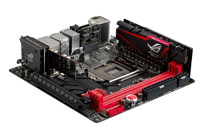
One of the highlights of ASUS’ ROG Computex Press Event was the announcement of the Maximus VII Impact, the successor to the popular mini-ITX ROG Impact range of motherboards. Today the motherboard is officially released from ASUS HQ, with stock coming to regions shortly. We reviewed the Maximus VI Impact last year and was appropriately impressed by the effort to include so many features in the mini-ITX platform – ASUS is hoping that this Z97 upgrade kicks it up a notch.
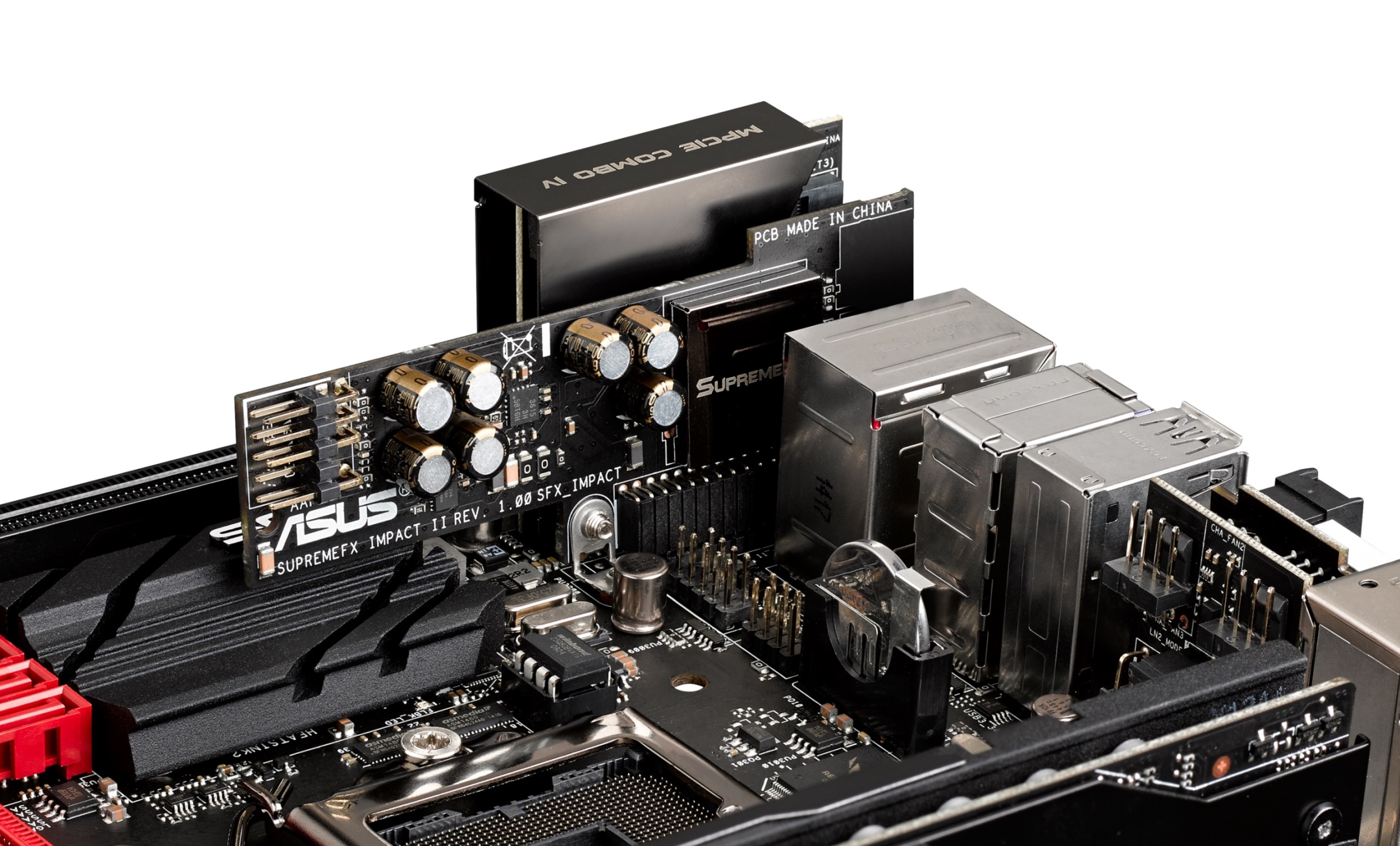
Similar to the Maximus VI, the order of the day is extra PCBs in order to add features. The power delivery is upgraded to the ROG 9-series design, and the audio add-on SupremeFX card moves up with fewer filter caps in a more optimized output. The mPCIe Combo moves up to revision four which includes a PCIe 3.0 x4 M.2 slot and a mini-PCIe slot with a bundled 802.11ac dual band WiFi module. Note that when the M.2 slot is occupied, the PCIe slot will reduce to PCIe 3.0 x8, although our previous testing of a similar feature shows no frame rate difference at 1080p.
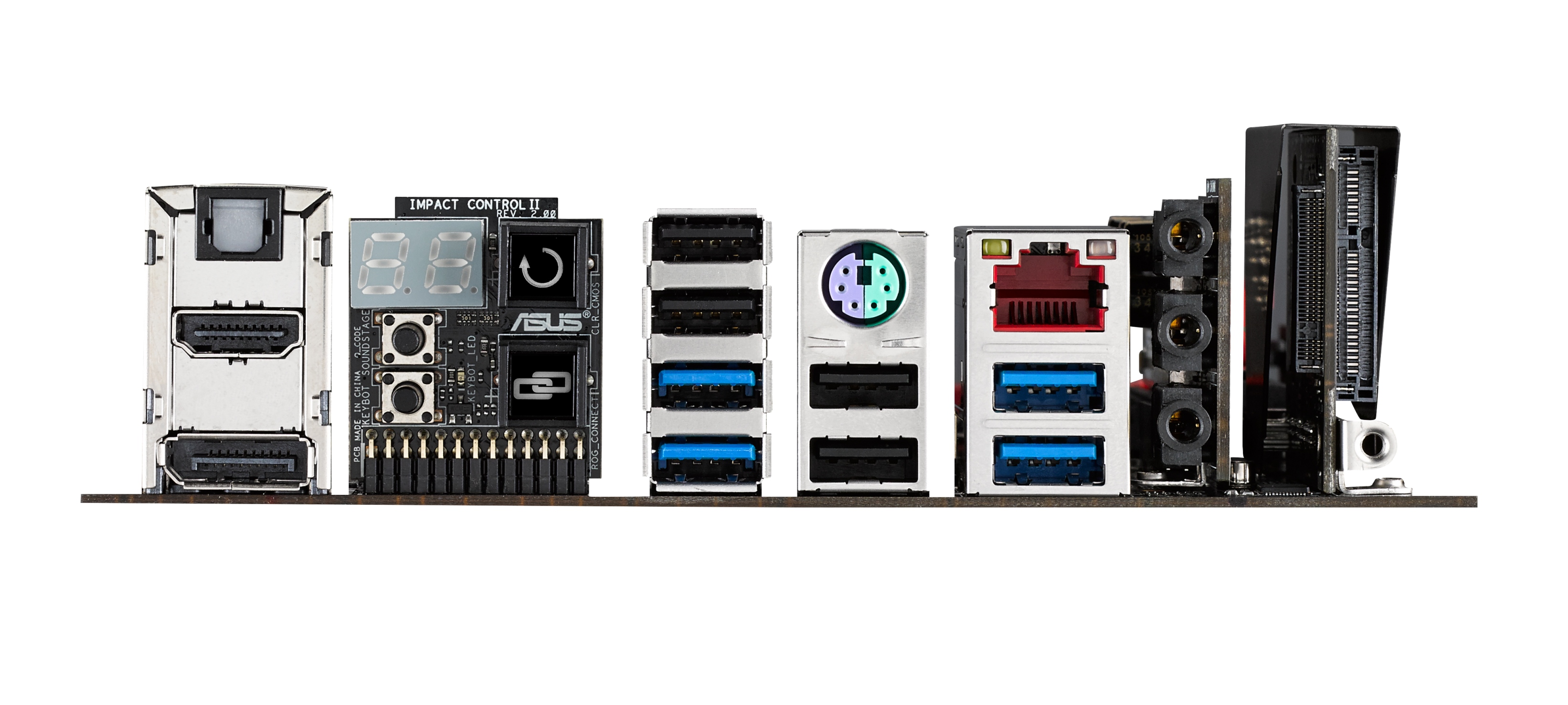
The Impact Control on the rear panel uses the same two-digit debug as the previous version, along with ROG Connect and a Clear CMOS button, but the two buttons included are for the KeyBot and SoundStage functionality introduced with the Maximus VII range. KeyBot is a feature to enable macros with any keyboard with the ASUS software, and SoundStage acts as a configurable op-amp that modifies various aspects of the audio output to be more suited for various styles of gaming.
Interestingly enough the rear of the Impact Control is another PCB, holding two 4-pin fan headers to compliment the 4-pin CPU fan header on the top left and the chassis header on the right of the motherboard. Also of note is the rear panel, where a single block of USB ports uses two USB 3.0 ports and two USB 2.0 ports – this configuration I have not seen on a motherboard before and could pave the way for something on most motherboards for the future.
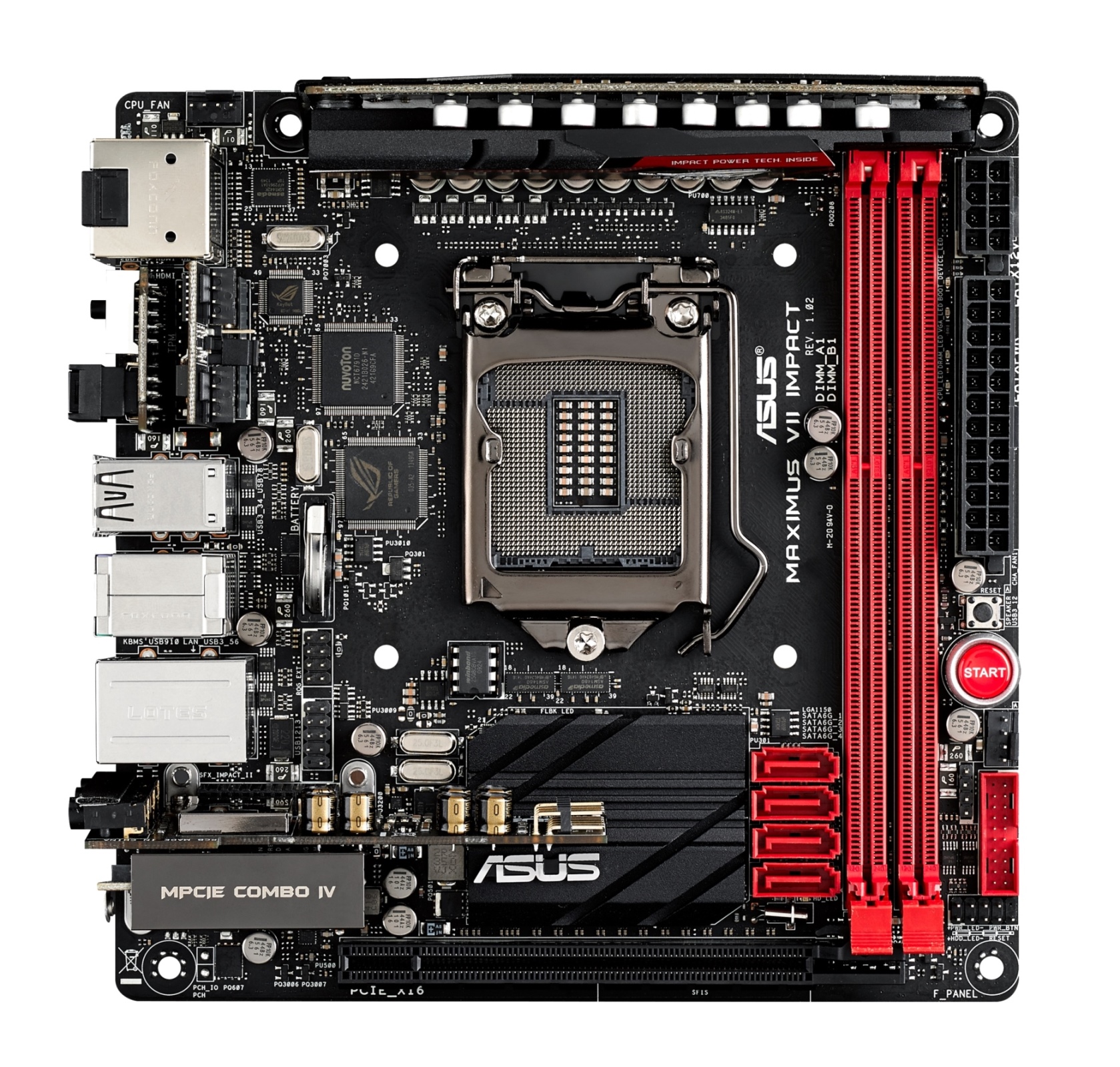
The DRAM slots use single side latches on the power delivery side, and the power connectors are gladly on the outsides of the motherboard. This follows the start button, a fan header and a USB 3.0 header. The front panel header is also on the right side of the DRAM slots. The SATA 6 Gbps ports are unfortunately just inside the DRAM slots and all in the same direction, perhaps causing issues with trying to remove locking cables.
The socket area is up against Intel specifications, suggesting that CPU coolers might be up against the power delivery or tall memory modules. The audio is buffeted by Sonic Rader II, an onscreen representation of directional audio, and networking comes via the 802.11ac WiFi and an Intel I218-V with GameFirst III.
We are awaiting information from ASUS’ US office for pricing and availability.


26 Comments
View All Comments
owan - Thursday, August 14, 2014 - link
At the same time, there really isn't much of a need to have the full 16x 3.0 lanes on the primary PEG slot. With a board this small, with this much going on, trace routing may have been a real factor as well.bebimbap - Thursday, August 14, 2014 - link
I always felt the M.2 on gen 3 would be best served on a ITX platform you could use the back side of the motherboard like Asrock did, and now you don't need space in your case for the ssd, or the mounts that go along with them. I almost feel the memory should go on the back side of the motherboard too. It could be closer to the socket, but I'm not sure how much of an engineering challenge that would be esp since most dimms are populated on both sides. Things like LAN chips, or the ROG management chips could also go on the back side too. This would free up space for more stuff like dual LAN.iTzSnypah - Thursday, August 14, 2014 - link
I don't see why ASUS didn't put the RAM slots right above the PCIe slot. Seems like a much better use of space.Ian Cutress - Thursday, August 14, 2014 - link
The issue here is specifications for the data lines. If you start moving the DRAM slots, you then have to adjust the signal lines around from their pins (which might be on the other side of the CPU) which influences the noise, performance and margins for overclocking as they pass by other data and power signal lines. The more you adjust where the pins are, the more you break compatibility if you don't compensate, and then re compensate for each microcode update. This is why Intel has a memory support limit (e.g. DDR3-1600) and anything other than that, they don't cater for, and why OEM motherboards typically often only support the memory frequency listed by Intel. ASUS do a fair amount of simulation for DRAM support and overclocking, but for something that significant you either break support (and people complain why random chinese OEM DRAM doesn't work) or have to wait until Intel makes the change/adjusts the next platform.ZeDestructor - Thursday, August 14, 2014 - link
Interestingly though, why not use SO-DIMMs rather than full lenth DIMMs? With the recent influx of high-end SO-DIMMs in recent times, DDR3-2133 SO-DIMMs are not that rare anymore.WithoutWeakness - Thursday, August 14, 2014 - link
It's an ROG board. This is ASUS's flagship mITX board and they wouldn't dare cripple it with SO-DIMM slots when competitors are sure to put full-size DIMM slots on their boards. 90%+ of people who buy this board will put 8-16GB of 1600/1866 RAM in it there and would be served just as well with SO-DIMM slots. However the remaining 10% will want to stick in DDR3 3000+ and OC the hell out of it and that's just not going to happen with SO-DIMMs.owan - Thursday, August 14, 2014 - link
In addition to the trace length and other specifications, the RAM slots occupy nearly the full length/width of the board. Where above the PCIe slot are they supposed to go? The space you're talking about is not only occupied by the PCH, mpcie slot, and sound system, but is in the same area as the rear I/O, which is valuable real estate. Placing the RAM slots anywhere other than where they are right now doesn't even make sense from a layout standpoint, let alone the technical hurdlesDanNeely - Thursday, August 14, 2014 - link
In addition to what Ian said about the signalling challenges, which could be worked around by rotating the socket too I suppose, unless you're willing to give up some expansion ports there isn't enough room to fit full size DIMMS left to right on a mITX board. The board is square, so you'd have the same equally tiny clearance left-right as you do top-bottom, and IO connectors are deeper front to back than the tiny sliver of space not taken by the DIMM.Morawka - Thursday, August 14, 2014 - link
Ram needs to be as Close as possible to CPU Socket for low latency. They made the right choice.kwrzesien - Thursday, August 14, 2014 - link
I would gladly give up the Start button on this mITX ROG to get a pair of SATA ports next to the USB 3.0 header.