GIGABYTE Z97X-UD5H Review: Choose Your Storage Option
by Ian Cutress on May 14, 2014 9:00 AM EST- Posted in
- Motherboards
- Intel
- Gigabyte
- Z97
GIGABYTE Z97X-UD5H BIOS
For Z97, the graphical BIOS ecosystem (either UEFI or EFI) has the opportunity for incremental updates. This might be fully fledged adjustments graphically, the addition of new features or the results of the engineers internally flexing some talent. For GIGABYTE, the Z97 BIOS in general uses the same topology from Z87 – a high definition mode on top of the classic mode from Z77. The main difference is the use of a ‘Startup Guide’ akin to an easy mode when you first enter the BIOS:
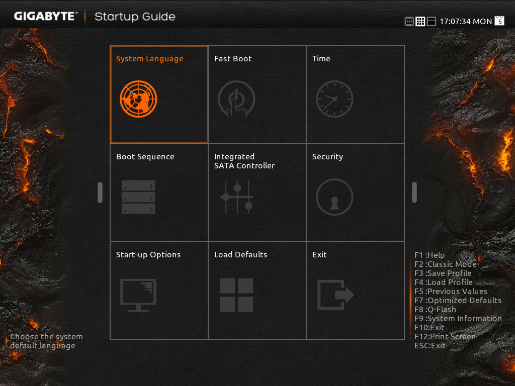
The options in the startup guide include Fast Boot options, Boot Sequence adjustment, SATA adjustment, security, start-up options (which mode to start in) and basic time adjustment. Unfortunately I have to become highly critical to this easy mode: if I had no idea what system I was dealing with and I moved into this BIOS, the only thing I now know about the system is that it is a GIGABYTE system. There is nothing on the front page about the CPU, the Motherboard, the speed settings, the temperatures or the BIOS revision. It is only because I have used GIGABYTE BIOSes before that I understand that pressing F2 will adjust to one of the other modes that will tell me this information. This menu uses a discordant amount of blank space for not very detailed icons and is not particularly that helpful as a startup guide beyond boot sequencing. One look at the Integrated SATA Controller icon gives me no idea what options are behind it, and for those new to the build-your-own desktop PC ecosystem, ‘Integrated SATA Controller’ means almost nothing. How about the word ‘Storage Options’?
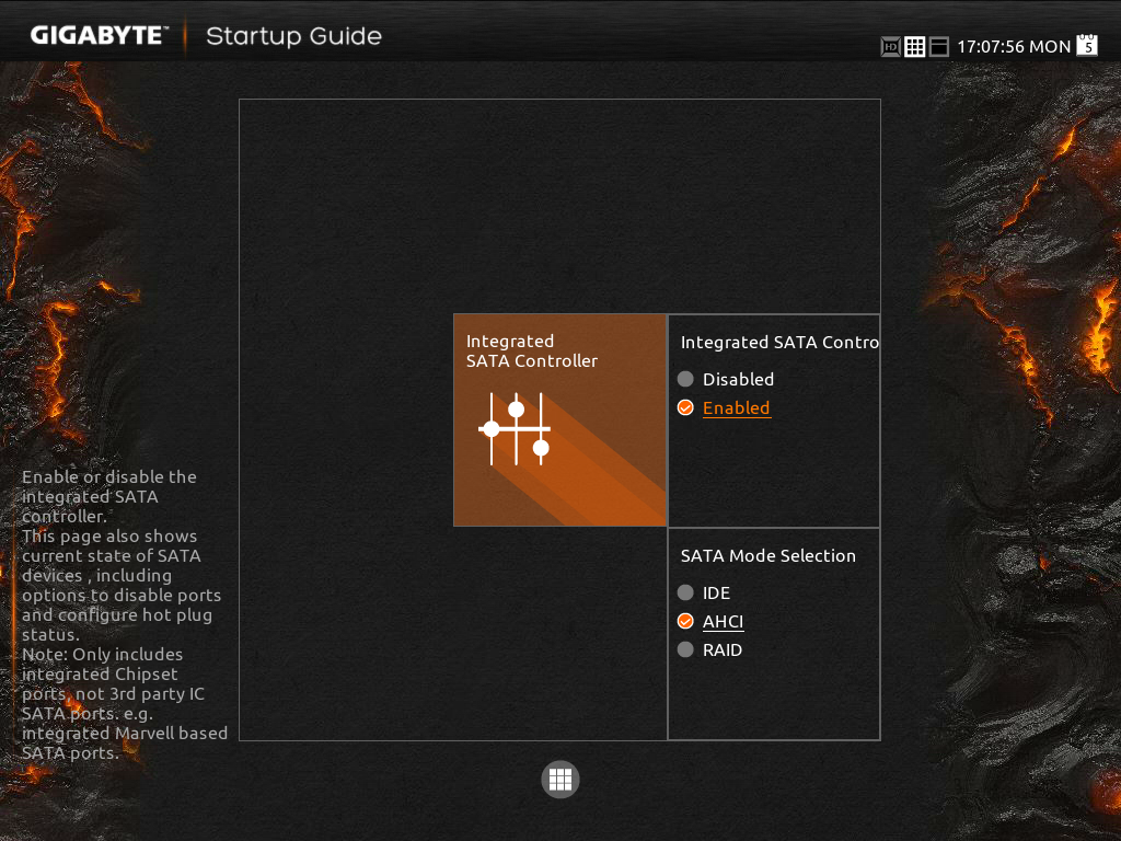
When a user clicks one of the icons the other options fade away and others take its place relating to the option chosen. Here the Integrated SATA Controller offers two options, enabling (one would wonder why it would need to be disabled in a startup guide) and the other is SATA Mode selection. Aside from the image above having text clipped, the information on the help description on the left does not correlate with the options on the right. Aside from being slightly unreadable (grey text on grey/black background), there are no options for hot-plug status as mentioned, and the text says this option only covers chipset ports. Chances that a new user would know which are or are not the chipset ports is anyone’s guess, however this is a graphical BIOS and the opportunity to put in a basic image to identify the relevant ports is missed.
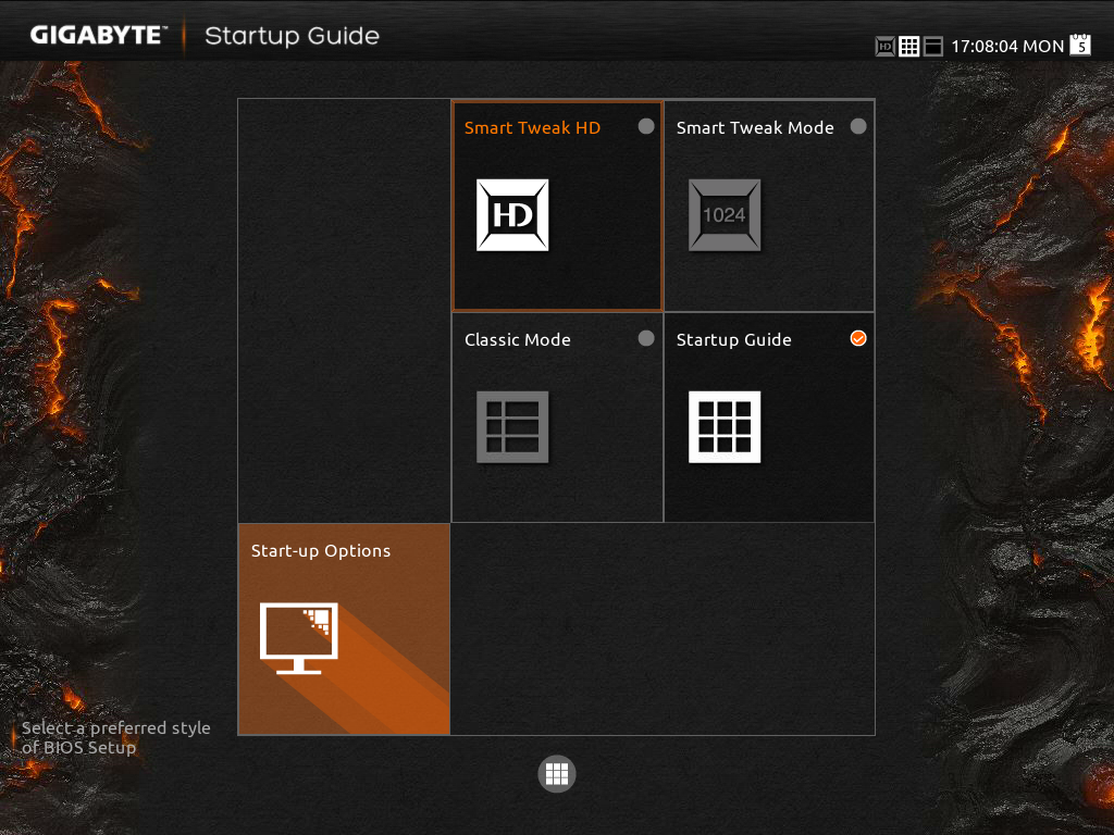
The Start-up Options tab gives the four modes which a user can set for future booting: the Startup Guide, Smart Tweak Mode/HD and Classic Mode. Note that when a BIOS is flashed to a later version, this option has to be reset. Unfortunately there is nothing GIGABYTE can do about this. However, the Smart Tweak and Classic modes are those that we saw on Z87, the first being a full 1920x1080 HD platform that shows all the information we need:
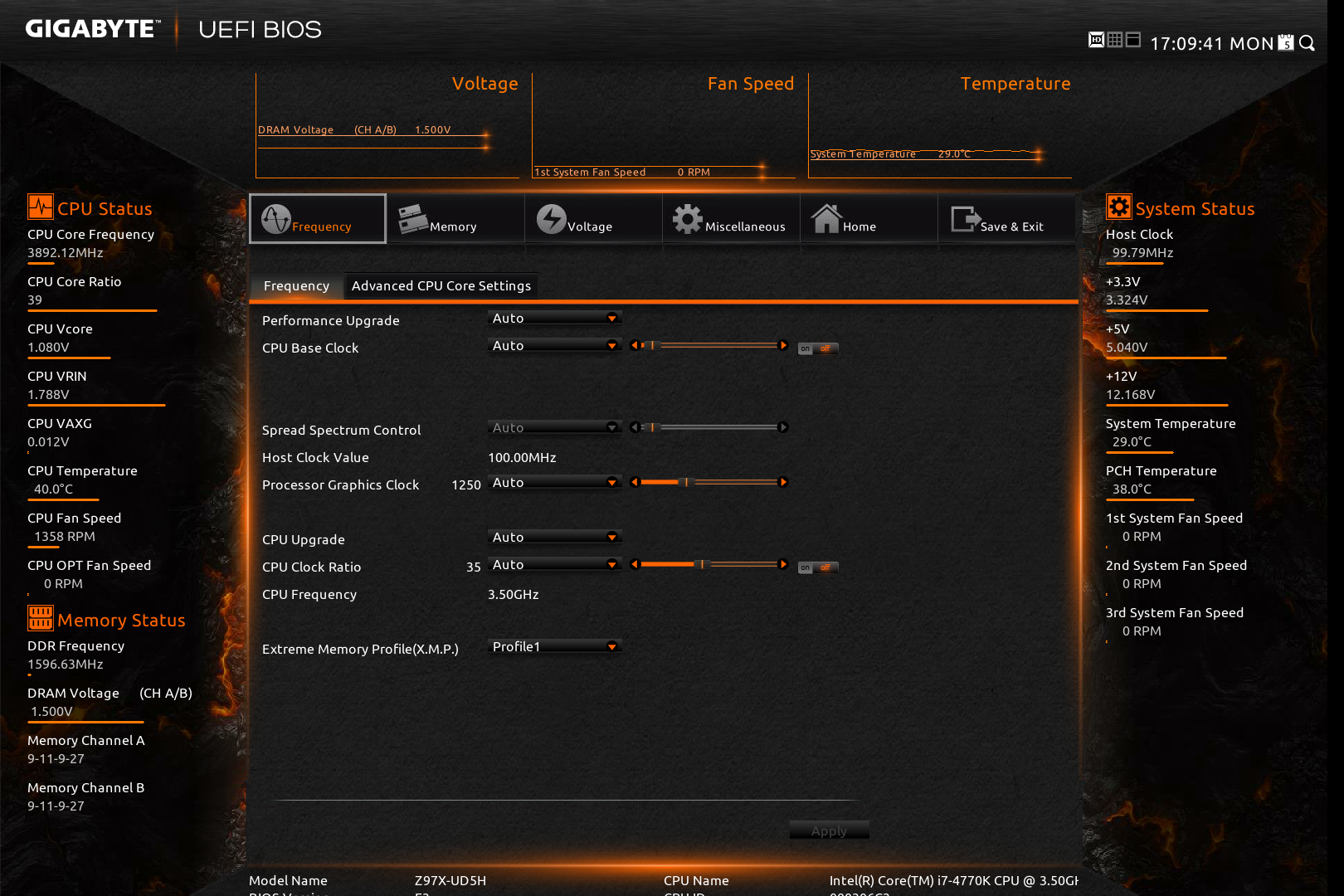
Unfortunately taking screenshots on my 1440p monitor cuts off some of the bottom of the BIOS, but it does show fully on a 1440p monitor. The information at the bottom and around the sides is just what we need in a BIOS – model names, frequencies, CPU installed, memory installed, memory speeds, temperatures, voltages, fan speeds, the whole lot. While I still have a mild dislike of the color scheme (I find it hard to focus on relevant data when quick glancing), the menus themselves are slightly rearranged better than on Z87.
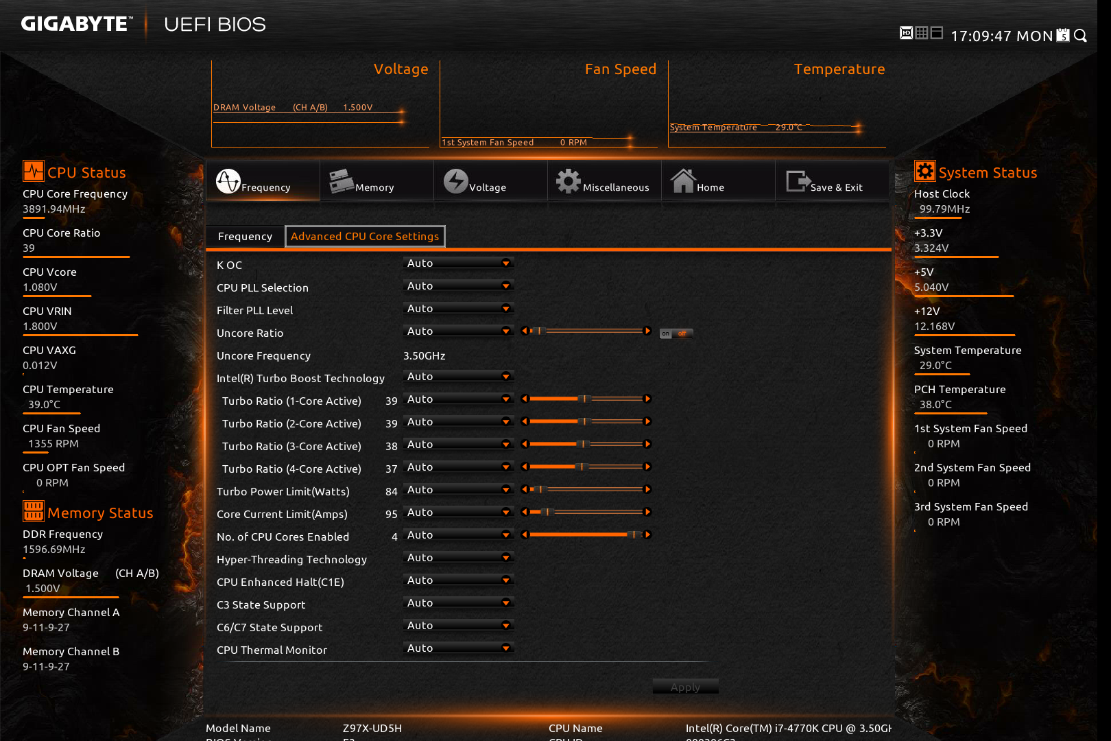
Shown above we have the Frequency Tab, which splits into the frequencies for overclocking, and the Advanced CPU Core Settings. In this menu users can apply frequency overclocks on the CPU, the IGP and enable XMP. The Advanced CPU Core Settings menu opens up the options into more detail including turbo rations, power limits and C-states:
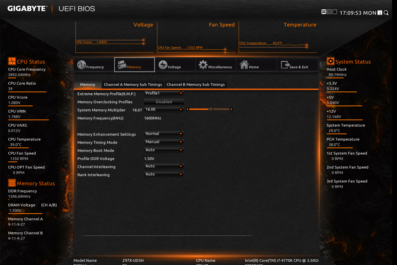
Similarly moving to the Memory main tab gives the advanced memory options, with a further tab for sub-timings:
The third tab relates to the advanced voltage options. Users of the Classic Mode in previous GIGABYTE BIOSes will notice that these three main tabs in Smart Mode mimic the main OC options from Classic Mode. This is an important level of integration, allowing users that are more accustomed to the older design to get up to speed on the new design because the two are laid out the same.
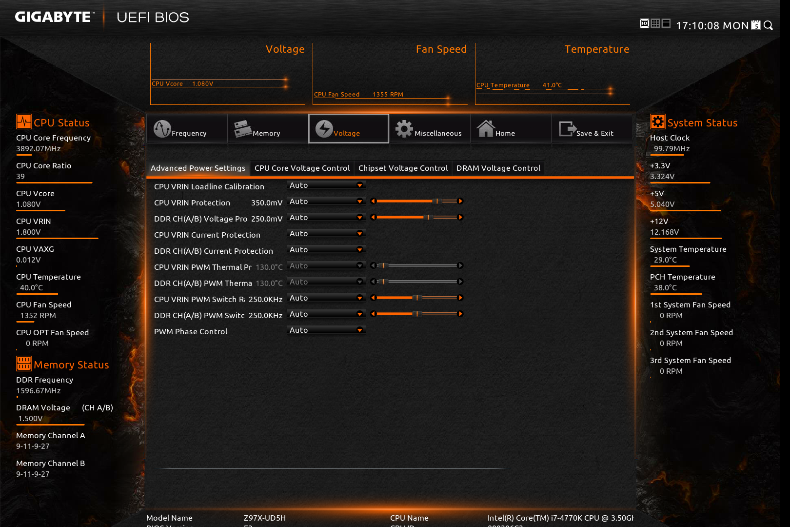
The voltage tabs are split into power settings (load line calibrations and thermal protections), CPU core voltages (VCore, VRIN, RING voltage, VCCSA), Chipset voltages and DRAM voltages. One point to note is the text overflow issue in English shown above – some options are too many characters for the designated spaces to hold, and yet there is plenty of blank space to the side unused.
The Miscellaneous tab offers a couple of the more obscure settings as well as PC Health, including the fan controls. For another generation GIGABYTE is giving BIOS fan controls as a function of PWM value/ºC. This is an unexplained metric in the BIOS (making it harder to understand from a user experience perspective), but I will try here.
Each fan header on the motherboard can apply a power from 0 to 255 to a fan. The fan will speed up according to the power profile of the fan (e.g. nothing until 10% power, then linear increase – this is determined by the fan design, not the motherboard). The fan power is not a direct linear correlation relationship to the fan speed, however the gradient of the power increase can be controlled in the BIOS. Thus a choice of 0.75 PWM value/ºC will increase the power of the fan by 0.75 units every degree Celsius that the CPU increases.
Given the leaps and bounds that other motherboard manufacturers have made on the fan front in the BIOS, as well as GIGABYTE’s own efforts on fan controls in the OS, I was hoping that the BIOS fan control would have been improved for Z97, however it is the same method as previous generations.
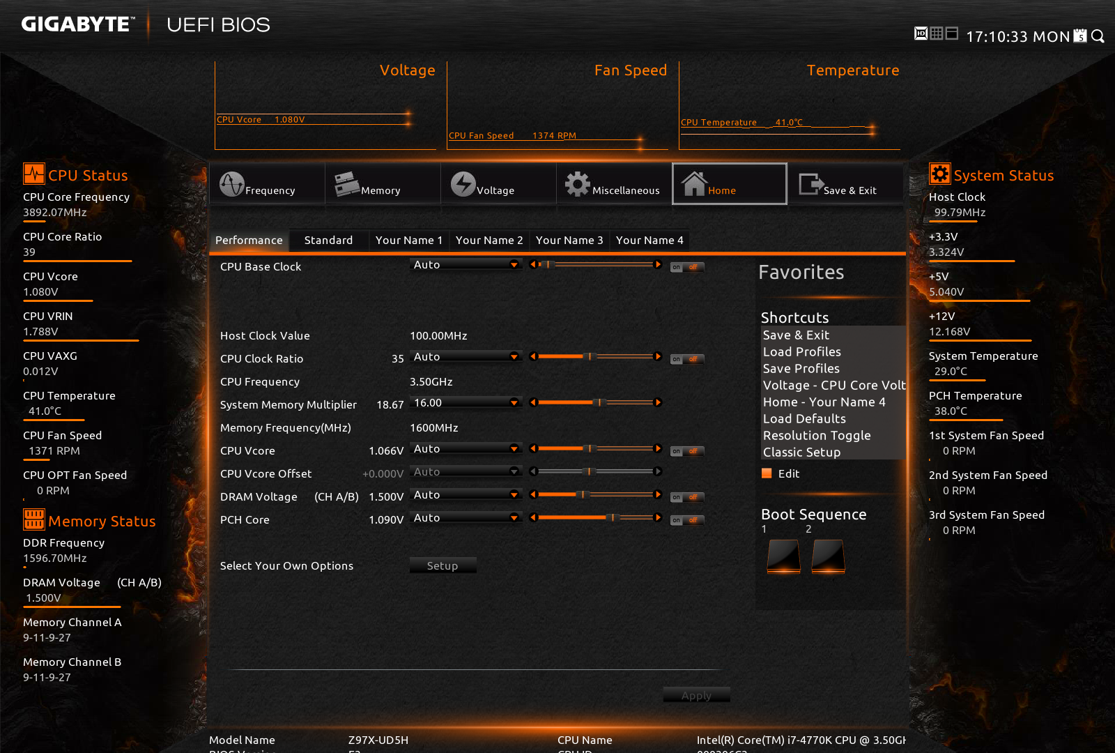
The Home screen is what GIGABYTE wants the HD BIOS to actually jump in to, which it did back with Z87. Here we have a group of overclock options such as BCLK, Clock Ratio, DRAM Multiplier and voltages. Almost everything most overclockers will need! The next tab along the line is labeled ‘Standard’ and offers options such as display output and SATA options. The ‘Your Name 1/2/3/4’ menus are the custom menus that allow users to pull options from other menus and place them into a custom menu. This was also introduced with Z87, however I think the menus GIGABYTE offers here will cater for almost everyone.
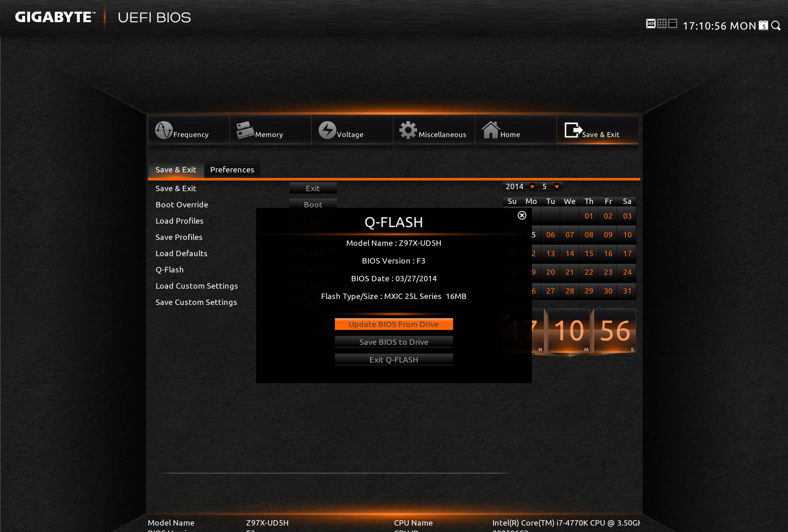
Updating the BIOS while in the BIOS uses GIGABYTE’s Q-Flash interface. Attach a drive to the USB 2.0 port with the BIOS file in the root drive to ensure compatibility and ease of use.
The other mode in the BIOS is classic mode.

We have gone through Classic mode in many reviews before [1,2,3,4,5] so I will not dwell on it here, but Classic mode tends to be the go-to option for many enthusiast overclockers. I feel this is because (a) it has been part of the GIGABYTE ecosystem for a number of years and they are used to it, and (b) due to the differing contrast it is a lot easier to read. It also happens to have a lot of the peripheral options:

For a full visual outlook of the BIOS we tested, see the gallery below.
With the new graphical BIOS there are many different ways a motherboard company can adjust the BIOS to be more interactive, but sometimes the graphically simpler interfaces are the easiest to use. There has to be the right leap from old to new for everyone to change.


53 Comments
View All Comments
Ian Cutress - Wednesday, May 14, 2014 - link
At this point, it is more up to the motherboard manufacturer and what they implement.The chipset diagrams will show you how the slots are arranged, and which can be used at the expense of others. We will try and add these as we go forward.
As for protocols, it is all AHCI right now.
Jon-Tech - Wednesday, May 14, 2014 - link
I wanted to ask about USB controllers. Are all the USB 2.0 ports using one controller? Are the USB 3.0 ports on the same controller? Also from the sounds of it, the extra USB 3.0 ports are just using a hub rather than an extra controller? Due to my setup I often run into USB bandwidth issues with lots of ports on one controller. So I'm looking at motherboards that have as many as possible for more flexibility and none of the review sites ever seem to mention how many there are!Regarding the z97 chipset, it appears that the xHCI Host Controller supports up to 6 USB 3.0 and 14 USB 2.0, this sounds like one controller. It also has two EHCI Host Controllers which support up to 14 external USB 2.0, though it doesn't look like any of the motherboards are using these. From the sounds of it this motherboard runs all the ports off the single controller? That strikes me as being daft and therefore unlikely, could you shed any light onto what the actual USB controller set up is please? I'm also unclear on how USB affects the PCIe lanes...
repoman27 - Thursday, May 15, 2014 - link
The Z97 chipset contains one xHCI which supports 14 USB ports, up to 6 of which can be USB 3.0. It also contains 2 legacy EHCI host controllers which can be used in lieu of the xHCI for USB 2.0 ports, but there are still only external connections for 14 USB ports total.With this board, it appears that Gigabyte has connected a motherboard header and the two back panel USB 3.0 ports above the HDMI port directly to the PCH xHCI, and then used a Renesas USB 3.0 hub chip to expand an additional PCH xHCI connection to support the other four back panel ports.
The PCH is connected to the CPU via a DMI 2.0 x4 link, which is equivalent to PCIe 2.0 x4, and thus provides a maximum of 16 Gbit/s less protocol overhead of total bandwidth for all PCH attached devices. Obviously the nominal bandwidth of just 6 USB 3.0 ports is greater than that. What isn't so obvious is how the various controllers within the PCH are connected to the PCIe bus internally. From the benchmarks I've seen of previous chipsets, it would appear that the xHCI only has the equivalent of an x2 connection. This still makes it one of the fastest USB 3.0 controllers out there since the only discrete controller I know of with an x2 back end is the Etron EJ198. Seeing as most motherboard manufacturers use discrete controllers with x1 back ends and connect them to PCIe lanes coming from the PCH, the performance generally sucks. If you need more than 785 MB/s of USB 3.0 bandwidth, you'd be better off buying a card like the HighPoint RocketU 1144C and sticking it in a slot that uses some of the PEG lanes coming from the CPU.
Jon-Tech - Thursday, May 15, 2014 - link
Thanks repoman, you've been the most insightful into this from all the various places I've asked! That HighPoint card looks spot on though it's rather pricey, especially considering my old mobo has 3 controllers on it for the 2x USB 3.0 and 12x USB 2.0. Though I only know the amount of controllers cause I have it and can check.Seems the only way I'm going to actually find out controllers per motherboards is to ask owners on forums to check for me. It's a really quick test that reviewers could do and its just as annoying it's never listed in the official mobo specs! Alternatively I could buy and try them out for myself though that doesn't seem practical.
Adriak - Wednesday, May 14, 2014 - link
Why are there still (conventional) PCI slots on motherboards? Didn't they become obsolete when PCIe arrived in 2004? I understand these slots are likely added for legacy reasons, but are people still using PCI cards? What type of cards are they? Was the ISA bus supported for this long after it was effectively rendered obsolete? I am genuinely curious.Nathan539 - Wednesday, May 14, 2014 - link
This would save me some money for my new comp that im buildingpeterfares - Wednesday, May 14, 2014 - link
Are people still using PCI devices on consumer boards? What could you possibly need to add that goes into PCI for home use?fluxtatic - Thursday, May 15, 2014 - link
Sound cards. If you're not using the Asus Xonar or a Turtle Beach card, odds are good your discrete card is PCI.Luay79 - Thursday, May 15, 2014 - link
Do you lose the 16 lanes for the single video card if you use M2/SAta Express SSDs?DanNeely - Thursday, May 15, 2014 - link
No. See the block diagram at the bottom of the first page. The 16 CPU lanes go to the 16x physical slots. The M2/SataExpress connectors use lanes from the southbridge.